Monitoring Devices
These kits, designed by BillSF, originally appeared in Hack-Tic, the Dutch hacker magazine.
FM Wireless Transmitter
We at 2600 tested this wireless FM transmitter thoroughly, and can safely say that it is well worth your time and effort to build. Most FM transmitters claim ranges of up to a mile. While this may be true, we often find the maximum range to be far less than expected. We used two fresh alkaline 9-volt batteries and were able to overpower other FM stations from up to 300 feet.
Although this may not sound impressive, it is when you consider that we were competing with powerful FM stations putting out up to 50,000 watts. The transmitter can reach much further when it does not have to compete with other stations. It will also work better if it is used outdoors in a high place.
Although this transmitter can be used as a "bug," we have found a much better use for it. Find a supermarket that is playing an FM radio over a loudspeaker. In all likelihood, your taste in music will differ from those who own the supermarket. Use the transmitter to overpower the existing station and transmit your own music. You can easily modify the device to accept the audio output of a portable tape playing device.
The transmitter has a power of 20 mW and can be adjusted from 80 to 130 MHz by slowly turning the screw (with a plastic "tweak" stick) on C3 (4-40 pF). If you wish to change the frequency outside these limits, the rule is: twice as many windings on the coil will cut the frequency in half.
By upping the battery voltage to 12 or 15 volts, the transmitting power is also raised. The power supply has to be very well stabilized so it is best to use batteries instead of a transformer. Never connect more than 18 volts if you care about your transistors.
Expect to take at least an hour building the transmitter. You will want to construct the device on a small breadboard. Do not use a soldering iron of more than 30 watts. Your best bet is to purchase a soldering iron with a pencil-thin tip. Make sure that the two transistors (Q1, Q2) and C1 (10 µF) are facing the right way.
The coil is extremely important. Wrap insulated, unbraided wire 6-3/4 turns around a cylindrical object approximately 3 mm in diameter. A 1/8" drill bit will suit the purpose. Magnet wire is the best choice.
The piece of wire shown in the diagram is your antenna and should be approximately 27 inches (69 cm) long. Use a flexible, insulated piece of wire and remember that the antenna will ultimately determine how far the device transmits.
Do not even think about going to RadioShack to purchase your supplies. First of all, RadioShack does not carry all of the parts that you will need. Although you could substitute similar transistors for the ones that are used, keep in mind that the circuit was specially designed to work at optimum efficiency with the parts used.
Secondly, RadioShack uses inferior parts and will overcharge you. We know that you probably want to start construction right away, and RadioShack may be the closest and most convenient supply of electronic parts, but you will be wasting your time and money if you go there. If you are serious about building the device, then be patient and order the parts from electronics firms listed in the back of Popular Electronics or similar magazines. Order at least two of everything so that you will have spares in case you mess up.
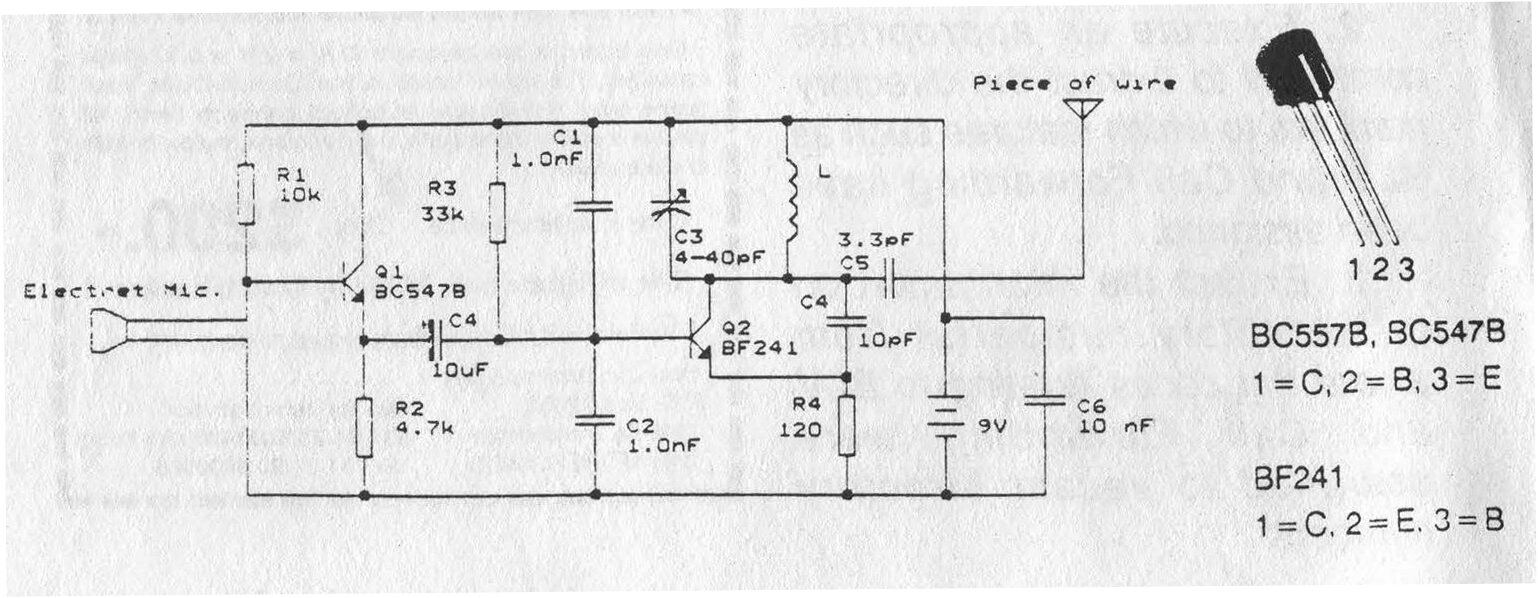
FM Wireless Transmitter - Parts List Resistors Values Colors R1 10.0 kΩ Brown, Black, Orange, Gold R2 4.7 kΩ Yellow, Violet, Red, Gold R3 33.0 kΩ Orange, Orange, Orange, Gold R4 120.0 kΩ Brown, Red, Brown, Gold Capacitors Values Notes C1 10.0 µF Polarized electrolytic capacitor C2 1.0 nF C3 4-40 pF Variable capacitor (Tuning) C4 10.0 pF C5 3.3 pF C6 10.0 nF C7 22.0 pF C8 1.0 nF Transistors Type Industry Name Q1 NPN BC547B Q2 NPN BF241 Coil: Insulated, unbraided 1 mm wire coiled 6-3/4 times on a 3 mm air core. Antenna: Flexible and unshielded, 69 cm long. Breadboard: The smaller the better! Microphone: Electric microphone Misc: Battery snap(s) Breadboard: The smaller the better! |
FM Telephone Transmitter
The FM telephone transmitter is essentially the same circuit as the FM wireless transmitter except that it is modified to take its input and power from a telephone line.
The transmitter has a power of about 5 mW, somewhat less than its sister transmitter. The LEDs are there to stabilize the power; they're not just there for show. The device also uses a full-wave rectifier so that you do not have to worry about polarity when you connect it to a telephone line.
Once the transmitter is in place, it will only transmit when the receiver is lifted.

FM Telephone Transmitter - Parts List Resistors Values Colors R1 47.0 kΩ Yellow, Violet, Orange, Gold R2 1.0 MΩ Brown, Black, Green, Gold R3 47.0 kΩ Yellow, Violet, Orange, Gold R4 4.7 kΩ Yellow, Violet, Red, Gold R5 100.0 kΩ Brown, Black, Yellow, Gold R6 33.0 kΩ Orange, Orange, Orange, Gold R7 120.0 kΩ Brown, Red, Brown, Gold Capacitors Values Notes C1 10.0 nF C2 1.0 nF C3 1.0 nF C4 4-40 pF Variable capacitor (Tuning) C5 10.0 pF C6 3.3 pF C7 22.0 pF Diodes Industry Name D1 1N4148 D2 1N4148 D3 1N4148 D4 1N4148 D5 LED D6 LED Transistors Type Industry Name Q1 PNP BC557B Q2 PNP BC557B Q3 NPN BCS47B Q4 NPN BF241 Coil: Insulated, unbraided 1 mm wire coiled 6-3/4 times on a 3 mm air core. Antenna: Flexible and unshielded, 69 cm long. Clips: Alligator clips to attach the device to the telephone line. Breadboard: The smaller the better! |