 |
|
|
|
|
|||||||
| LP20MHz | C1,4=180p | C2,3=330p | L1,3=583n | L2=650n | C1,4=68p | C2,3=270p | L1,3=473n | L2=758n |
| LP200MHz | C1,4=18p | C2,3=33p | L1,3=58.3n | L2=65n | C1,4=6.8p | C2,3=27p | L1,3=47.3n | L2=75.8n |
| HP100MHz | C1,4=47p | C2,3=18p | L1,3=61.8n | L2=51.5n | C1,4=82p | C2,3=22p | L1,3=78n | L2=49n |
|
|
||||||||
| LP20MHz | C1=18p | C2=82p | C3=120p | C4=330p | L1=120n | L2=270n | L2=430n | |
Low pass and high pass filters can be arranged as shown, using the same
pcb holes of the canned ones. Don't forget to isolate the 'red' nodes from
ground!
 |
|
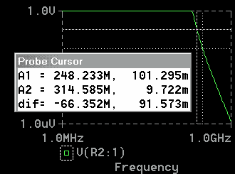
You can see the simulated performance of the theorical Chevyshev filters
for the RF section in the graphs shown.
 |
 |
A more realistic model with coupling between coils, even when using
toroidal ones, will have a response with spurs, and limited high frequency
attenuation.
Althought isn't difficult to built these filters you probably will
need to tune its coils to get a good shape. The Butterworth ones are less
sensitive to component tolerances and easier to build. If you aren't sure
about your success adjusting them, then save your time and headaches and
buy them.
For the buffer section the Bessel filter are preferred, even having
a much slower roll off and that non-simetrical components values are used.
Its impulse response are better, and at this stage we are processing baseband
digital data, so is better to have an approximate flat group delay in the
filter's passband. The BT=1.8-0.9 product (depending of the period of manchester
encoded signal) of this filter are probably very loose. With a Gaussian
or raised cosine type filter will result in a lower bandwith with a small
increase in the time domain ringing. Below you can see the effect of the
filter in the digital signal(blue) plus IF leakeage(red), giving a nice
output (green). Click on the image to see an expanded view.
 |
 |
The measured insertion loss is 46dB@145MHz for all my homebrewed Bessel 20MHz low pass ones, better that the 40dB specified by the MCL parts. Althought the insertion loss of a MCL PLP-5 I also tested was more than 70dB@145MHz, for sure due to the very good shielding and low inductance to ground of the package. The time domain reponse althought was much worse due to overshot and ringings (with the proportional data rate). The meassured time domain output of the Bessel filters had a very nice shape, near identical to the simulated, since for a 1Vpp signal, -46dB is just only 5mVpp, and the IF leakage are for sure much lower than 1Vpp. So this insertion loss are good enought here.
Below you can see the test fixture I used to meassure the filter's frequency
and time domain characteristics. The attenuator are needed to isolate the
signal source from the reflected signal of the filter, and the load to
terminate the filter in its characteristic impedance.
Also are shown the filter's parts, that have been hand picked and wound
using a dip meter, althought if you have a signal generator also could
measure with it more precisely. One coil is single layer, and the others
are double layer. All experimentally made. You could expect about a 25%
tolerance without to meassure them, that isn't too bad for a Bessel filter
like this as shown in a Monte Carlo analysis.
But you should test one at least.
|
|
|
| 120nH | 14 single layer or 5+5 double layer |
| 270nH | 7+7 double layer |
| 430nH | 11+11 double layer |
From upper-left: Butterworth LP 20MHz filter, MCL PLP-5, homebrewed
filter frame glued from turned pin stock, Bessel LP 20MHz filter and parts.
 |
 |
I've also drawn a small PCB for the low and high pass filters built with smd parts.
To download: