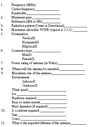
When choosing antennas for wireless systems, engineers
must evaluate gain, radiation pattern, VSWR, polarization, and operating
frequency
By Joseph Reisert, Technical Consultant, Astron Antenna Co.
An antenna's performance determines the quality and the continuity of data flow in both the transmit and receive paths of a wireless system. Unfortunately, selection of the antenna is often deferred to the latter phases of a program and the quality of the selection is usually driven by price instead of value. Worse yet, the actual performance of the antenna in the system is seldom verified until after the system is installed.
As most engineers know, the antenna is one of the most important components in any RF communication system. If the antenna is used for both reception and transmission, a 1 dB increase in performance represents a 2 dB system improvement--1 dB on receive side and 1 dB on transmit side. This dual-path effect makes antenna performance a key element in the overall system that should not be understated.
When selecting antennas for a wireless system, engineers must be familiar with all major aspects of an antenna. The following 10 questions help engineers gain this understanding:
- What is the operating frequency range of the system?
- How much gain is required?
- What kind of radiation pattern is desired?
- What is the maximum allowable VSWR?
- What polarization is required?
- What type of connector interface is required?
- How much power will the antenna have to handle?
- Where will the antenna be mounted?
- Is a radome required?
- What is the lifetime of the antenna?
What is the operating frequency range of the system?
Before any antenna can be specified, the engineer must
first know the approximate center frequency of the system as well as the
operating bandwidth of the system. These two parameters will help engineers
determine if they can use off-the-shelf products or if they need a custom
solution.
Operating frequency, to some extent, also dictates the size of the antenna. Size is particularly important when planning an installation where adequate space must be available on a tower or other location. Since antennas are larger at lower frequencies and smaller at higher frequencies, it is important for the engineer to closely consider operating frequency during antenna selection.
How much gain is required?
Antenna performance is primarily established by its gain.
Gain must always be measured against a known reference. Unfortunately,
there are many "so-called" gain references. Choosing the wrong reference
could cost the engineer up to 2 dB in performance.
Most commercial antenna suppliers specify gain in dBd
(gain over a half-wave dipole). The half-wave dipole is one of the simplest
and most efficient antennas. It is relatively easy to construct and has
a very predictable radiation pattern similar to that of a donut. This is
why most commercial antenna suppliers reference gain to a half-wave dipole
(Table 1).
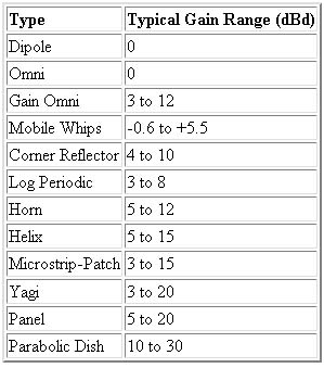
Another reference, especially used at microwave frequencies, is dBi. This term refers to gain over an isotropic radiator; a theoretical antenna that radiates equally well in all directions (such as the Sun). If an antenna is specified in dBi gain, it will appear to have approximately 2.15 dB higher gain than dBd. This may be a nifty way to impress the customer but it does not mean that the engineer obtains more gain if dBi is the reference.
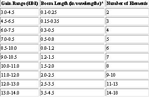
Gain influences the type and size of an antenna (Table
2). The higher the gain, the larger the antenna. As a rule of thumb,
doubling the gain (a 3 dB increase) will increase the size of an antenna
by a factor of 2-3.
What kind of radiation pattern is desired?
Radiation pattern is one of the most critical elements
in the antenna selection process. As we discussed, gain establishes antenna
performance. Radiation pattern, however, has a direct affect on gain within
an antenna. The only way to increase gain within an antenna is to concentrate
power in a narrower beamwidth. The narrower the beamwidth, the greater
the gain.
A good conceptual example of this concentration is the
vertical omnidirectional antenna. It is often used for line-of-sight communications
with mobile stations spread out in various directions usually restricted
to the horizon. If greater performance is required in these systems, the
antenna gain can be increased by using a collinear-type omnidirectional
antenna. This antenna decreases the vertical beamwidth and concentrates
more power on the horizon where it will be most beneficial (See Figure
1).
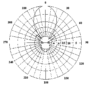
Typical radiation pattern of a gain omnidirectional
antenna
Panel antennas, yagi antennas, parabolic dishes, and patch arrays can also be used to optimize radiation pattern and increase gain in line-of-sight communication applications. Panel antennas are used to optimize a sector (typically 90 to 120 deg. in azimuth) with a narrow elevation beamwidth. Yagis, parabolic dishes, and patch arrays are usually designed for high gain applications because they offer narrow beamwidths in both the azimuth and the elevation plane.
What is the maximum allowable VSWR?
VSWR represents the degree with which an antenna is matched
to system impedance. Since most modern antennas do not require any tuning
for optimum performance, VSWR is one of the easiest parameters to measure
in an antenna.
Most modern antennas, receivers, and transmitters are designed for peak performance when operating into a 50 W transmission line. If VSWR is too high, the transmitter power and received signal strength may be reduced within the wireless system.
The typical commercial standard for maximum allowable VSWR across the entire bandwidth of a system is 1.5:1. This means that the antenna impedance must be somewhere between 37.5 and 75 W.
Engineers should specify maximum VSWR and operating frequency bandwidth when specifying the antenna. In general, a VSWR of 2:1 or greater is considered unacceptable since it increases losses in the transmission line. A VSWR below 1.5:1 should also be avoided. Decreasing the VSWR below 1.5:1 will often be expensive and will have little noticeable performance improvement.
What polarization is required?
Most wireless systems use vertical, horizontal, or elliptical
[right hand circular (RHC) or left hand circle (LHC)] polarization techniques.
In some instances, the polarization selection is determined by the installation
site, with the antenna oriented to provide the best performance. If this
is anticipated, engineers should use antennas that provide mounting capabilities
for all polarization techniques.
Selecting the proper polarization for the system can enhance the overall performance by minimizing the interference from adjoining systems. For example, an engineer can obtain 20 dB isolation by installing a system orthogonal to other systems in the area.
Proper polarization is especially important for in-building applications such as wireless private branch exchange (WPBX) or wireless data collection systems. In these applications, handheld devices move around a room or warehouse with the fixed antenna often pointing many degrees off-axis. To solve this problem, fixed antennas often employ circular or elliptical polarization techniques with a hemispherically shaped pattern. These polarization techniques trade off high gain for reasonable gain in all directions.
What type of connector interface is required?
Proper connector selection is another important step
in the antenna selection process. When selecting connectors, engineers
consider the following rules:
- If a system is operating below 300 MHz, a UHF connector will generally be satisfactory although it is difficult to waterproof.
- Above 300 MHz, the UHF connector induces VSWR mismatches. Type N, TNC, and BNC connectors are preferred at higher frequencies because they maintain a good VSWR. These connectors feature low loss and can handle moderate power (250 W) up to 1 GHz.
- If high power and/or low intermodulation distortion is required, especially where multiple antenna systems are operating in close proximity, the new large 7/16 DIN connector may be required.
- If small size and low power operation from 1 to 10 GHz is anticipated, the SMA connector may be preferred.
How much power will the antenna have to handle?
Generally speaking, this is the least important antenna
parameter, especially in receive-only or low-power (less than 50 W) transmitter
applications. In general, the power-handling capability of an antenna is
a function of the connector type and the transmission line (if it is an
integral part of the antenna).
Engineers should specify the average power that will reach the antenna. If the transmitter is emitting pulse or peak power, it is important to provide the antenna supplier with the peak power level.
Where will the antenna be mounted?
In general, mounting issues are impacted by how well
the antenna will perform and survive in its operating environment. Antenna
mounting is also directly affected by local zoning ordinances and regulations.
In order to properly mount an antenna in a wireless system, engineers must
closely evaluate these environmental and regulatory issues.
Once the environment and laws are properly evaluated, engineers must ask the following questions: How will the antenna be mounted? If the antenna is attached to a tower or mast, what is the diameter of the pipe or mast? Will the antenna be rear or center mounted?
For an exterior mount, the integral strength of the design must be considered. Engineers must know whether or not the mount can withstand wind, ice, heat/cold and other extremes. Engineers must also asses whether or not the major components within an antenna (the feed, the radome, and connectors) can withstand stress.
The materials and hardware used in the construction of the antenna are also important in exterior mount situations. Exterior-mounted antennas should use durable materials such as aluminum and stainless steel.
In-building applications can be torturous during the mounting process. Will a desktop antenna survive constant handling and having books and coffee cups dropped on it? Should the antenna be mounted to a wall or a ceiling? Will the antenna have to be disguised? Will a wall mount be used as a target? As wireless applications continue to grow, in-building applications will continue to grow and challenge the ingenuity of the designer.
Is a radome required?
Radomes serve two purposes in antenna systems. First
they protect the antenna. Second, they hide the antenna.
Increasingly, the visual impact of an antenna is being considered when making a choice between products. By using radomes, engineers can color or shape antenna systems to improve aesthetics. This has proven very effective in indoor and outdoor applications.
Panel antennas are usually enclosed within a radome to protect the elements and/or any printed circuit boards (PCBs). Yagi antennas equipped with radomes usually are more of a detriment than a value. The wind load on the antenna is significantly increased and protection offered to the antenna itself can often be offset with proper design of the feed system and the directors.
What is the lifetime of the antenna?
Simply put, a cheap antenna will last long enough to
win the job and lose the customer while a good antenna will be warranted
to meet performance specifications. The quality of the mechanical design,
the individual elements of the antenna, and the final antenna product should
be judged on how well the product meets the mechanical and environmental
requirements of a specific wireless system.
Author's Note: This information should only be used as a guideline for selecting an antenna.
Joseph Reisert, Technical Consultant, Astron Antenna
Co., 22560 Glenn Drive, Suite 114, Sterling, VA 20164. Phone: 703-450-5517;
Fax: 703-450-9753.
The Top Antenna Questions to Answer Before Calling an Antenna Supplier
This form provides an easy guide for specifying wireless antennas. Before calling an antenna supplier, an engineer should answer all of the questions listed below.