Grounding kits and arrestors protect base stations against the damaging electrical surges caused by lightning strikes.
By Jonas Aleksa and Christopher Stockman, Andrew Corp.
Lightning strikes can be damaging to wireless base stations. The electrical current generated by these strikes (see sidebar) can send extreme power surges throughout a wireless system, causing electronic products to overload and malfunction. Although base station designers can't do anything about thunderstorms, there are preventive measures that can be taken to protect a site from damage inflicted by lightning.
Grounding, bonding, shielding, and surge suppression are the four commonly applied methods to protect wireless infrastructure from indirect effects of lightning. The challenge for engineers, however, is to integrate these practices and select the right products to produce a reliable system design.
The first step to choosing a lightning protection approach is to identify the parts of a system that need to be protected as well as the paths that lightning currents and voltages can use to reach this equipment. Grounding, bonding, and shielding reduce surges by providing additional paths for lightning currents to flow to earth. Surge suppression, on the other hand, is important for critical, sensitive equipment and equipment connected by cables over long distances.
Protecting RF equipment investment and revenue from lightning damage requires proper transmission line grounding. An unprotected transmission line is a conduit to radio equipment for lightning transients. Installing both grounding kits and surge arrestors will help manage lightning effectively to safeguard equipment.
Grounding Kits
Grounding kits are the first line of defense against the damaging effects of lightning. These kits are attached to transmission lines at various points along the cable support structure (Figure 1).
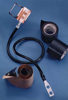
Figure 1: To defend against lightning strikes, engineers should install grounding kits at various points along the cable support structure.
In essence, grounding funnels lightning transients off the line's outer conductor. Each transmission line, at minimum, should be grounded at the top and bottom of the vertical run and at the entrance to the equipment shelter. For longer vertical runs, additional grounding should be installed at 60 m (200 ft) intervals.
When implementing grounding kits in wireless base stations, it is important to use product that offer durable designs. Ground strap connections must withstand extreme outdoor conditions while still maintaining solid mechanical connections to maximize protection.
The key is to maintain low electrical contact resistance. A well-designed grounding kit should conform to industry standards such as IEC 1024-1, Protection of Structures Against Lightning, and MIL-STD-188-124A, Military Standard for Grounding, Bonding, and Shielding. Some specific requirements of these standards include:
- A 16 mm2 cross sectional area for copper bonding conductors
- Galvanically compatible bonds
- Cleaned bonding surfaces
- Resistance of less than 1 mW per bond
- Encapsulated bonded surfaces
The requirement for encapsulated bonds is critical to both product design and installation. Moisture infiltration will speed corrosion, increase resistance, and lessen the effectiveness of the grounding kit.
The point most vulnerable to corrosion is where the grounding is attached to the transmission line. A good grounding kit will supply adequate sealing materials, such as butyl rubber and plastic tapes, to seal this connection. Grounding products with braided wire conductors are likely to have corrosion problems as the capillary action of the conductor wicks moisture into the connection.
Installation
Proper installation of grounding is essential to establish a reliable, low impedance path for lightning current. The first step in the installation process is determining where to employ grounding products. After determining the location for grounding, a small section of cable jacketing must be removed to accept the cable attachment strap. In wet conditions, the exposed outer conductor should be dried immediately before attaching the strap.
When attaching the strap, all hardware must be tightened according to manufacturer specifications. Overtightening must be avoided to prevent cable damage that may result in a degradation of system return loss. Good grounding kit design uses calibrated straps, expansion joints, or spring clips to help ensure proper tightness. The grounding kit must also be sized for the cable being installed.
When attaching the grounding kit to the tower or ground bar, the downconductor should be as short as possible and oriented as straight downward as possible (Figure 2). Long and/or curved leads increase impedance and reduce grounding kit effectiveness.
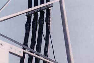
Figure 2: To effectively install grounding products, downconductors must be oriented as straight as possible in order to reduce the possibility of long or curved leads.
The final requirement in the ground kit installation is attachment of the termination lug. A small section of jacketing must be carefully removed from the copper conductor to avoid nicking. Then the lug must be screwed or crimped in place. Crimp lugs should be sealed to the conductor with heat shrink tubing. The ground wire terminal can be attached to a tower member bus bar, angle adapter attached to a tower member, or tower downconductor.
When installing the termination lug, use of hose clamps to attach ground terminals is not recommended. In addition, aviation color paint, but not the zinc plating underneath it on the tower, or oxidation from the surface of the bus bar should be removed in the area where the termination lug will be bolted. A layer of conductive grease applied to this area will ensure good electrical contact when the lug is bolted into place.
Surge Arrestors
Sensitive microwave equipment requires an additional measure of protection against lightning transients. In these cases, surge arrestors (Figure 3) are installed to remove transient current that may be induced onto the inner conductor of coaxial cable before it reaches the equipment.

Figure 3: Surge arrestors provide additional protection against lightning strikes in wireless base stations.
Quarterwave stub (QWS) and gas tube (spark gap) surge technologies have been proven very effective in RF applications. Each has distinct characteristics that lend themselves to certain applications better than others. The proper surge arrestor for a given application adds the final level of lightning protection to a transmission line system.
The QWS surge arrestor operates similar to a bandpass filter, where a tuned stub shorts the center conductor of the device to its body, allowing only a specified frequency range to pass. This shorting stub is effectively one-quarter wavelength in size at the center of the desired frequency band. When a lightning surge enters a QWS arrestor, it sees the quarterwave stub as a direct path to the outer conductor and earth ground.
Since QWS arrestors are frequency specific, they exhibit low VSWR and low insertion loss. These arrestors react instantly to a lightning surge but allow a small level of energy proportional to the magnitude of the lightning strike to pass (throughput energy). The heavy duty construction of the shorting stub provides high operating power handling capability and is known for its ability to survive multiple lightning strokes, making it ideal for high power and/or lightning prone sites. The QWS arrestor, however, cannot be used in applications that require a DC bias.
Gas Tube Arrestors
Gas tube surge arrestors also divert lightning current off the center conductor of a coaxial cable. This technology differs in that it allows passage of a wide frequency band, typically 0 to 2500 MHz, making it ideal for applications that use tower top devices that require a DC bias fed through the center conductor of the coax.
Where the QWS arrestor is frequency sensitive, the gas tube arrestor is voltage sensitive. The gas tube device appears as open until a specified voltage threshold is reached at which time it changes to a low impedance surge arresting state. Again, a small amount of throughput energy will pass as a finite amount of time is required for the fast rising current of a lightning surge to activate the gas tube.
Since the gas tube arrestor is voltage sensitive, average operating power, VSWR level, and DC bias will influence gas tube selection. It is important to follow manufacturer recommendations on gas tube selection to achieve the proper power rating for a given system.
Gas tube surge arrestors are typically rated to protect against lightning impulses up to 20 kA. Since there is no way of knowing whether or not a gas tube may be compromised from a high-level lightning surge, periodic maintenance is required to replace surge arrestors or the gas tubes at locations of a suspect lightning strike.
Surge arrestors are available with common interfaces, such as 7/16 DIN or Type N connectors, for easy integration into any transmission line system and should be installed on all transmission lines as close as possible to the equipment they are intended to protect. Systems that use tower top-mounted amplifiers (TMAs) should have a surge arrestor installed at the top and bottom of the coax run.
Prior to installation, all grounding surfaces should be cleaned and free of oxidation. Most surge arrestors ground through their body. Some use a keyed bulkhead, while others depend on a flange or stud that must be fastened with provided hardware to the site's grounding system.
A popular practice is to fasten the grounding mechanism on all surge arrestors to a single copper bulkhead or multiple copper bus bars, both of which are bonded to a master bus bar and earth ground. Proper torque must be applied to the hardware on the arrestor-to-grounding bar connection to ensure a low resistance connection. A special washer is often included with bulkhead mounting arrestors to help achieve proper torque. A new washer should be installed whenever the arrestor is reinstalled after removal for system maintenance.
Performance Testing
Surge arrestors can be readily tested for microwave performance by using any vector network analyzer (VNA). For QWS arrestors, VSWR (return loss) and insertion loss, specified by the manufacturer, will be for the operating bandwidth only. The shorting stub characteristics on systems with QWS arrestors require that fault location testing be performed by using a VNA with time domain capability. Some test equipment manufacturers refer to this type of fault location testing as frequency domain reflectometry (FDR).
The lightning management practices described above for RF transmission lines are just a part of a complete site-grounding plan. Towers, guy anchors, fences, telco lines, AC power lines, and other equipment within the site must also be tied into an earth grounding system.
Many manufacturers of radio equipment outline specific requirements on the use of buried conductors, placement of ground rod, and bonding of connections. Following their requirements to achieve a low resistance earth grounding system is vital to the overall effectiveness of lightning management.
Jonas Aleksa, Engineering Manager, and Christopher Stockham, Product Line Manager, Andrew Corp., 10500 W. 153rd Street, Orland Park, IL 60462. Phone: 708-349-3300; Fax: 708-349-5222.
References:
1. Freeman, Roger L., Reference Manual for Telecommunications Engineering, second edition. New York: John Wiley & Sons, 1994.
2. Guthrie, A.K., "Learning to Live With Lightning," Communications, May 1977.
3. Global Hydrology and Climate Center, National Aeronautics and Space Administration Marshall Space Flight Center, July 1997.
4. Uman, Martin A., "Natural Lightning," IEEE Transactions on Industry Applications, Vol 30, 1994.