Base stations are the heart of today's cellular, PCS, and wireless local loop (WLL) systems. They provide the precise synchronization of voice and data signals needed to properly operate a wireless system.
When developing base stations, system designers face many concerns. They are continually looking at building better amplifiers as well as improving transmitter and receiver portions of the system. Crystal oscillators, used in transmit and receive operations and in clock boards, are also a key concern for design engineers.
A wide range of technologies--such as CDMA, TDMA, and GSM--make up the wireless industry. As a result, base stations require several types of quartz oscillators for operation. The most critical is the oven-controlled crystal oscillator (OCXO).
All feedback oscillators, including OCXOs, can be represented as servo systems operating under a condition where instability occurs. When instability occurs, the oscillator's system equations break down and an oscillation takes place at a limit cycle. The amplitude of this cycle is limited by the nonlinearities of the system. A block diagram of a feedback system shows that manipulations of the transfer functions G(s) and H(s) can allow representation of just about any closed-loop system, including an oscillator (Figure 1).
Figure 1: A block diagram of a feedback system shows that manipulations of the transfer functions G(s) and H(s) can provide a representation of an oscillator.
The transfer function T(s) has zero factors in the numerator and pole factors in the denominator. The pole factors are of importance to engineers. The eigenvalues of these pole factors provide the frequencies at which oscillations may occur. The general function T(s) has a denominator of 1 + G(s)H(s). To determine the frequency where oscillations occur, the engineer must locate the frequency where G(s)H(s) = -1. (This assumes that that G(s) and H(s) are frequency dependent functions.) At this frequency, the function T(s) becomes infinite and oscillations may occur.
But difficulties now occur for the engineer. The system is at a singularity that is not described by the pre-existing transfer function T(s). As a result, limited knowledge is obtained by this closed-loop analysis other than an estimate of the oscillation frequency.
If the Laplace variables decay to a steady state value, the transfer function T(jw) is obtained (Figure 2). As G(jw)H(jw) takes on a range of values in this plot, regions of negative feedback, positive feedback, and oscillation can clearly be observed.
Figure 2: In an OCXO design, the transfer function T(jw) is obtained when the Laplace variables decay to a steady state value.
Breaking the steady state system down further, G(jw) and H(jw) consist of some group of elements each having an overall net gain and phase shift characteristic (Figure 3). For oscillations to occur, the magnitude of all the elements around path P1 must equal or exceed 1, and the total phase shift must equal 0 radians or n x 2p radians (where "n" is an integer). This analysis can be done by opening the loop and analyzing the transfer function for these conditions. The engineer can then determine if and at what frequencies oscillations occur. In addition, the robustness of oscillations can be estimated from an analysis of the gain present at the oscillation frequency as well as from the shape and slope of the phase plot.
Figure 3: A closed loop system can be opened to test the transfer function.
Phase Slope and Stability Implications
When developing base stations, design engineers need OCXOs that provide high stability and accuracy. To meet these needs, oscillator designers take great care in controlling the phase angle in these devices.
Phase angle is critical because it essentially determines the frequency and stability of the oscillator. The high stability of an OCXO is directly attributable to the steepness of the phase slope at the frequency of oscillation. Stability is also attributable to the accuracy of this slope. Since the frequency of oscillation occurs where the phase function crosses zero, all the components of the oscillator loop affect the frequency of oscillation. Therefore, keeping all of the OCXO's components stable in impedance is a main concern for the oscillator designer. A shift in transistor junction capacitance or in an inductor can cause an undesirable change in the operating frequency of the oscillator.
To overcome these effects, resonators with very high reactance versus frequency functions within their bandwidths are used in OCXOs. This forces the loop phase slope to cross zero phase with a very high slope. Therefore, component instabilities or drifts can cause only very small changes in frequency because the steep phase slope supplies a new value of impedance for loop zero phase at only a slightly shifted frequency (Figure 4). For this reason, low-frequency, third- and fifth-overtone AT-, SC-, BT-cut crystal resonators are always used for best stability.
Figure 4: In OCXOs, low-frequency, third- and fifth-overtone AT-, SC-, BT-cut crystal resonators are always used for best stability.
Providing a high reactance slope (dX/dF), the resonator overwhelmingly controls the oscillator's frequency. Other phase-shift contributing components can only modestly affect frequency. For example, a 50 percent change in a capacitor value in the circuit may only cause a few parts in 107 change in frequency when using a 5 MHz third-overtone, SC-cut crystal resonator. However, design engineers generally seek stability in the 10-9 of 10-10 area for OCXOs. As a result, a 10-7 shift may be disastrous to an OCXO. The stiff resonator's job is to correct for phase variations in the loop. By doing this, the resonator will reduce the effect of drift, snaps, and other component temperature coefficients on the OCXO in order to maintain stability.
Stability and Phase Zero Crossing
A steep phase slope from the crystal is fundamentally important to good frequency control in oscillator designs. The oscillator designer must take great care in the overall design to keep the zero-phase frequency from shifting in order to get the ultimate performance required by today's wireless applications. The crystal must also be manufactured for extremely good long-term stability so that the resonator will feature very little frequency aging as time progresses.
Other outside influences such as voltage variations and load pulling must also be minimized in the design of an OCXO. To minimize outside influences, OCXO designers employ an extremely stable oven section that isolates the crystal and oscillator components from changes in ambient temperature.
Transmit And Timing Control
When implementing oscillators in wireless base stations, the overall goal is to provide the system with a frequency reference that does not drift outside the needed limits. Various factors of instability must be allotted for and periodically corrected out of the system. Representing the OCXO's output as F(t) = acos(vt + f), it is realized that a, v, and f), will change a bit as functions of time, voltage, and environmental stress. Thus, some amount of output frequency instability and inaccuracy occurs in an OCXO.
In transmitters, frequency aging (also called long-term frequency drift) is a major concern for base station designers. Other instability effects can be designed down to a point where they are often not a problem.
Aging drift can be negated in several ways. In one approach, a sufficiently stable, free-running OCXO is used without provision to correct the frequency. This technique can provide a very good reference (holding tens of parts per billion per year). But if required system accuracy is not fairly loose, the long-term drift may cause unacceptable frequency error after several years in service.
A second approach employs a mechanically adjustable OCXO. In this method, the OCXO is periodically adjusted to keep its frequency within the tolerance range for the system. However, this is a manual method. Human error may cause unreliability in the adjustments. In addition, the touch time associated with the adjustment process may be prohibitively expensive.
The third option employs an electronic frequency control (EFC). This is the preferred method from an oscillator design standpoint because troublesome mechanical trimmers are not used.
The final approach is an implementation where the OCXO drives a module that synthesizes the correct frequency from an oscillator. In this scenario, the oscillator is nonadjustable and may drift out of system tolerance limits. External correction is applied as needed through information from periodic measurements of the system's output against a known reference frequency, such as a GPS satellite signal.
The EFC Port
The EFC port is a critical interface between the oscillator and the host system. As a result, it is important to specify the adjustment voltage range, the frequency deviation range, polarity, the adjustment rate or bandwidth, the temperature coefficient of the control circuit, the ripple noise present on the control line, and the curve fit of the transfer function for this port.
When driving the EFC port, base station designers should take steps to minimize the noise on the control line. This noise will directly frequency modulate the oscillator and create sidebands.
The temperature coefficient of the supply voltage and control circuit must also be kept low. If not, the temperature coefficients from the EFC control line voltage will increase the drift of frequency versus temperature beyond what the OCXO inherently produces. The frequency deviation range should not be more than what is needed to pull the oscillator back to nominal frequency under all operating life conditions. Excessive deviation range will compromise the oscillator overall stability. Also, the base station should be designed to tolerate 10 to 15 percent linearity error in the EFC transfer function.
Since many base stations rely on digital-to-analog converters (D/As) to drive the EFC control port, opportunities exist to make use of mathematical fit approximations of EFC curves (Figure 5).
Figure 5: Since many base stations rely on D/As to drive the EFC control port, opportunities exist to make use of mathematical fit approximations of EFC curves.
Typically, some number is calculated to describe the linearity of the curve or departure from ideal. But this is of limited value to the base station designer. The calculation is a single number that does not provide any information specific to any point on the curve.
Instead, the oscillator supplier can curve fit the function and provide accurate information at all points on the curve. The curve fit data is presented as coefficients to a known equation allowing the user to make precise adjustments to the oscillator frequency through software control.
Successful Use
In order to successfully use an OCXO, engineers need manufacturers to establish the appropriate product specifications through an understanding of performance tradeoffs. Since a host of factors will affect stability, OCXO engineers need to look at the overall stability requirements for proper base station operation. By doing this, the designer can develop the best oscillator at the lowest cost.
From work done specifying numerous wireless OCXOs, Oak Frequency Control has developed a tree of instability factors to guide the development of OCXO specifications (Figure 6).
Figure 6: Oak Frequency has developed a tree of instability factors to guide the development of OCXO specifications.
From an overall system frequency accuracy need, a stability budget allocation should be made from the optimum design solution. In general, engineers need +/-20 PPB stability in PDC systems, +/- 50 PPB stability in GSM systems, +/-250 PPB stability in DAMPS systems, and +/-50 to +/-100 PPB stability in paging systems.
These are clear-cut limits of the frequency tolerance needs for broadcast or timing of system operation. Using, for example, the +/-50 PPB overall frequency tolerance requirement of GSM, a potential stability might look like (see table):
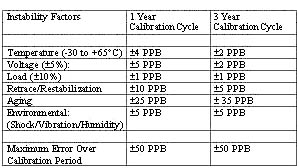
In this table, budgets are developed to accommodate one-year or three-year calibration periods. The oscillator's total allowable error has to be weighed against the system's ability to recalibrate the OCXO, thereby periodically removing the accumulated error due to aging. Frequent recalibration eases aging requirements and cost for the OCXO.
But this approach brings high maintenance costs. To reduce these costs, engineers can turn to OCXOs that provide better aging performance and longer calibration cycles. To obtain state-of-the-art aging performance and the long calibration cycles, base station designers should turn to OCXOs which employ custom SC-cut crystals in their resonator. These OCXOs can supply the needed tolerance frequencies without frequency corrections applied for periods of five years or more.
Dan Nehring, Precision Oscillator Engineering Manager, Oak Frequency Control Group, 100 Watts Street, P.O. Box B, Mt. Holly Springs, PA 17065. Phone: (717) 486-3411, Fax: (717) 486-5920. E-mail: dnehring@ofc.com