Switched-Beam and Adaptive-Array Techniques Reduce Co-Channel and Multipath Interference to Improve Coverage and Capacity in Wireless Systems
By Marc Goldburg and Michael Lynd, ArrayComm, Inc.
Design engineers are continually looking for solutions that increase coverage and capacity within a cellular or PCS system without the need for more cell sites. Re-evaluating antenna technology is one approach.
Traditionally, system designs have employed omnidirectional and sectorized antenna technologies in cellular and PCS systems. But these approaches are limited in terms of capacity by uncontrolled interference. As a result, more engineers are looking at smart antennas as an alternative for maximizing the performance capabilities of their macrocell in order to defer or eliminate the need for microcells.
What Is a Smart Antenna?
In truth, antennas are not smart; antenna systems are. Generally co-located with a base station, a smart antenna system combines the outputs of multiple antenna elements with signal processing capabilities to transmit and/or receive RF signals in an adaptive, spatially sensitive manner. In other words, a smart antenna system can automatically change the directionality of its radiation and/or reception pattern in response to the signal environment. This can dramatically increase the performance characteristics (such as capacity) of a wireless system.
Many of today's wireless systems employ sectorized antenna technologies, which shape the directional antenna pattern of a single element. Smart antenna systems take a different approach. These systems intelligently combine the outputs of multiple antenna elements. In doing so, they provide greater control over the base station's radiation and reception patterns.
The category of smart antenna systems embraces such terminology as intelligent, phased array, diversity, spatial division multiple access (SDMA), spatial processing, digital beamforming and adaptive systems. But, in the most general sense, smart antenna systems are categorized as either switched-beam or adaptive-array systems.
Switched-Beam Antennas
In terms of radiation patterns, switched-beam systems are an extension of the cellular sectorization method of splitting a typical cell. The switched-beam approach further subdivides macrosectors into several microsectors as a means of improving range and capacity. Each microsector contains a predetermined fixed-beam pattern with the greatest sensitivity located in the center of the beam and less sensitivity elsewhere. The design of such systems involves high-gain, narrow azimuthal beamwidth antenna elements (Figure 1).

Figure 1: Switched-beam antenna systems select one of several predetermined fixed beam patterns with the greatest output power in the remote user's channel.
The switched-beam system selects one of several pre-determined fixed-beam patterns with the greatest output power in the remote user's channel. These choices are driven by RF or baseband digital signal processing (DSP) hardware and software. The different beams can be formed through baseband signal processing or static RF combining networks.
When the mobile user enters a particular macrosector, the switched-beam system selects the microsector containing the strongest signal. Throughout the call, the system monitors signal strength and switches to other fixed microsectors in situations where it perceives a change in user location.
Adaptive-Array Systems
In addition to the conventional temporal processing (e.g., modulation) done at the base station, adaptive-array systems perform spatial processing. By adjusting to the various characteristics of an RF environment as they change (or the spatial origin of signals), adaptive-array technology can dynamically and continuously alter signal patterns in order to optimize the performance of the wireless system (Figure 2).

Figure 2: Adaptive-array technology can dynamically alter the signal patterns to near infinity in order to optimize the performance of the wireless system.
Adaptive-array systems use measurements from antennas and sophisticated signal processing algorithms to continuously refine an RF model for distinguishing between desired signals, multipath, and interfering signals. This model is then used to determine transmit and receive beamforming strategies. Adaptive-array algorithms are distinguished by the complexity of their models and their performance objectives.
Both switched-beam and adaptive-array systems attempt to increase gain according to the location of the user. But only adaptive-array systems (with a reasonably rich model) provide optimal gain while simultaneously identifying, tracking, and minimizing interfering signals.
What Makes Them Smart?
A simple antenna is designed for a simple RF environment. Smart antenna solutions, however, are required as the number of users, interferers, and propagation complexity grow. Their smarts reside in their DSP facilities.
Similar to the most modern advances in electronics today, the digital format for manipulating the RF data offers numerous advantages in terms of accuracy and flexibility of operation. Speech starts and ends as analog information. Along the way, however, smart antenna systems capture, convert, and modulate analog signals for transmission as digital signals and reconvert them to analog information on the other end. In adaptive-array systems, this fundamental signal processing capability is augmented by algorithms that are applied to control operation in the presence of complex operating conditions.
The benefit of maintaining a more focused and efficient use of the system's power and spectrum allocation can be significant. Smart antenna technology can improve the signal quality of the radio-based system through more focused transmission of radio signals while enhancing the capacity through active interference control. This leads to increased frequency reuse and improved signal quality.
Interference Rejection
Of all the benefits offered by smart antenna systems, interference rejection may provide the greatest benefit for the base station designer and system operator. An operator's revenues are based upon how many quality calls can be maintained by the system, and a system's capacity correlates to its ability to control interference. As a result, interference problems can be a big and costly headache for the design engineer.
Two of the bigger interference problems encountered in a wireless system are multipath and co-channel interference. Smart antenna systems help engineers curb these problems.
Multipath is a condition where the transmitted radio signal is reflected by physical features/structures, creating multiple signal paths between a base station and the user terminal. Conditions caused by multipath that are of particular concern are:
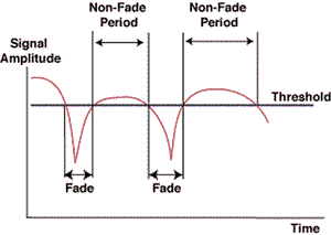
- Fading -- When the waves of multipath signals arrive out of phase, reduction in signal strength can take place. One example is a constantly changing, three-dimensional phenomenon called a fade (Figure 3).

Figure 3: A fade is a constantly changing, three-dimensional phenomenon. When a fade occurs, the received signal will fluctuate downward, causing a momentary degradation in quality.
Fade zones tend to be small, multiple areas of space within a multipath environment that attenuate a received signal as users pass through them. In fade zones, received signal strength will fluctuate downward, causing a momentary degradation in quality.
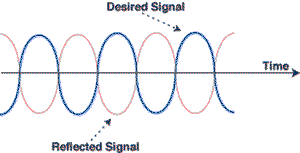
2. Phase Cancellation -- When waves of two multipath signals are rotated exactly 180 deg. out of phase, the signals will cancel each other out (Figure 4). While this sounds severe, it is rarely sustained on any given call (most air interface standards are quite resilient to phase cancellation). A call can be maintained for a short period of time with out a signal, although it results in very poor quality.

Figure 4: Phase cancellation occurs when the waves of two multipath signals are rotated exactly 180 deg. out of phase and momentarily cancel each other out.
Phase cancellation creates a bigger problem when the control channel signal is canceled out. When this occurs, a black hole -- a service area in which call set-up will occasionally fail -- is created in the system.
3. Delay Spread -- Delay spread happens when multiple reflections of the same signal arrive at the receiver out of sequence (at different times). This spread can result in intersymbol interference that the receiver cannot sort out. When delay spread problems occur in a system, bit error rate (BER) rises and eventually causes noticeable degradation in signal quality.
Co-Channel Interference
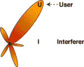
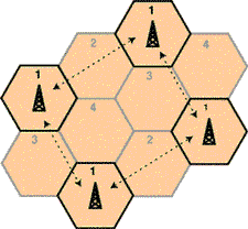
One of the primary forms of man-made signal degradation associated with digital radio, co-channel interference occurs when the same carrier frequency reaches the same receiver from two separate transmitters (Figure 5).

Figure 5: A primary form of radio signal degradation, co-channel interference occurs when the same carrier frequency reaches the same receiver from two separate transmitters.
Co-channel interference is the number-one limiting factor in maximizing the capacity of a wireless system and is the motivation for frequency reuse plans. To combat this interference, smart antenna systems not only focus directionally on intended users, but in many cases direct nulls or intentional non-interference toward known, undesired users.
How Smart Antenna Systems Work
Smart antenna systems enable a base station to effectively customize the beams they generate for each remote user based on their analysis of the signals they receive from the RF environment.
Switched-beam systems monitor for the location of strongest user signal and return energy in the greatest concentration to that location. In effect, on a particular traffic channel, switched-beam systems listen for the loudest signal in a microsector and send downlink signals back (base station to user) in real time to that same microsector.
In comparison, adaptive-array systems attempt to continuously respond to the RF environment. These systems build a model of the RF environment that may include information gathered about both users and interferers. Constantly updating this model, the system adjusts its strategies for transmission and/or reception to optimize performance according to set objectives such as signal power, BER, or signal-to-interference ratio.
Typically, the received signal from the spatially distributed antenna elements is multiplied by a weight--a complex adjustment of an amplitude and a phase. These signals are combined to yield the array output. An adaptive algorithm controls the weights according to predefined objectives.
Benefits/Tradeoffs
When selecting any wireless technology, it is very important for engineers to closely weigh the benefits and tradeoffs of that technology. This is especially true when selecting a smart antenna technology.
Integration is one of the key concerns in any wireless system. Commercially available switched-beam systems are designed essentially to retrofit widely deployed cellular systems. They are an add-on, or appliqué, technology that intelligently addresses the needs of mature networks. In comparison, adaptive-array systems represent a more fully integrated approach. They offer reduced hardware redundancy and improved performance, but with a greater impact on base station architecture.
Range and coverage are other obvious considerations. Both adaptive-array and switched-beam systems can increase base station range from 20 to 200 percent over conventional sectored cells depending upon environmental circumstances and hardware/software used. This added coverage can save an operator substantial infrastructure costs and lower prices for consumers.
Capacity is one of the most critical considerations for today's cellular systems. With limited spectral resources, capacity can only be increased through interference mitigation on both the uplink and downlink system connections.
Switched-beam antennas suppress interference arriving from directions away from the active beam's center. Since beam patterns are fixed, however, the amount of interference rejection is variable, and strongly dependent upon the fixed pattern and relative locations of users and interferers. Switched-beam solutions work best in minimal to moderate co-channel interference because they have difficulty distinguishing between a desired signal and an interferer. If the interfering signal is at approximately the center of the selected beam and the user is away from the center of the selected beam, the interfering signal can be enhanced far more than the desired signal. In these cases, signal quality is degraded. Even worse, if the interferer is more powerful than the user, the system can lock on to the interferer.
Adaptive-array systems, on the other hand, have continuously variable directivity patterns. This allows them to provide consistent levels of gain and interference mitigation to the dynamic RF environment. As a result, system planners can rely on an adapative-array system's processing gains to shrink reuse distances and thereby increasing capacity. Today's more advanced adaptive-array systems can accommodate multiple users on the same voice channel, creating a reuse of less than one.
Marc Goldburg, Manager of New Projects, and Mike Lynd, Marketing Communications Writer, ArrayComm, Inc., 3141 Zanker Road, San Jose, CA 95134. Phone: 408-428-9080; Fax: 408-428-9083.

• INDUSTRY NEWS
• COMPANIES IN THE NEWS
• MARKET TRENDS
• TEST TALK WITH KAREN OTTO
• MEMORY DESIGN
• THE WLAN BEAT
• TECHNOLOGY TODAY
• GLOBAL NEWSWIRE SUMMARY
• WEB RESOURCE CENTER