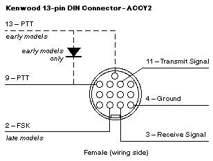
For radio models: Kenwood with 13-pin DIN connector - ACCY2
Wiring Diagrams Index | Ham Radio Articles Home Page
Manufacturers have been known to change their usage of pins, please compare diagrams shown with the product's manual. Pins not shown may be used for other functions. Damage may occur if wrong connections are made.
Pins are labeled with the number of the pin, followed by the descriptive name used in Chapter 5 of What is your TNC doing? FSK is discussed in the article Which Jack for HF Radio-to-TNC Cables?
Kenwood

Pin 2 (later models) - FSK
Pin 3 - Receive Signal
Pin 4 - Ground
Pin 9 - PTT
Pin 11 - Transmit Signal
Pin 13 (early models) - PTT
Early models - wire a small-signal diode (1N914 or equivalent) between Pin 13 and Pin 9
Note: Later models do not need Pin 13 connected. Early models have separate PTT pins for completing the circuit and for muting the mic. Both pins must be connected with a small-signal diode (1N914 or equivalent) as shown for early models. Check your manual.
Tip: The pins on this connector are very close together therefore difficult to solder. To make it easier, remove unneeded pins from the connector before soldering.
Wiring Diagrams Index | Ham Radio Articles Home Page
73 de ka5ztx gmedcalf@prairie.lakes.com | copyright 1995 gloria e medcalf
URL: http://prairie.lakes.com/~medcalf/ztx/wire/k13pin.html