by Glen Brisebois
Measuring the resistance of a device, for example a thermistor,
usually requires biasing it with a precision current source or combining it
with with several other precision resistors in a bridge. The circuit of Figure
1 shows how to use the new LT1168 instrumentation amplifier to
achieve a precision resistance-to-voltage conversion as simply as
possible. Normally, the resistor across pins 1 and 8 is the gain-set resistor and
the voltage across pins 3 and 2 is the variable to be measured. In this
case, however, the 1.25V reference establishes a fixed input voltage so that
the variable to be measured is now the resistance. The equation for
VOUT vs RT is
VOUT = 1.25V • 49.4k/RT.
Given the limitation on output swing (with the supply voltages shown), the
smallest measurable resistance is about 4.5k. The highest resolvable
resistance is limited to about 200M by the 300µV output offset voltage of
the LT1168. The 0.05% accuracy of the LT1634 is not an issue here,
because it is subtracted at the Ref pin of the LT1168 and only contributes to
gain error. Figure 2 shows output voltage vs temperature for 10k and 100k
(at 25°C) thermistors from two manufacturers. Thermistors are difficult
to linearize, so although the output is still not linear with temperature,
it can, at least, be read directly by an ADC and compared against a
lookup table. The circuit has good noise immunity but does not
tolerate capacitance at pin 1 or 8 and so is not ideal for resistive devices
placed remotely from the LT1168. 
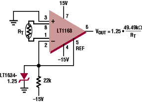
Figure 1. Simple resistance-to-voltage converter |
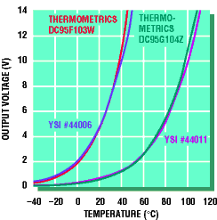
Figure 2. Output voltage vs temperature for thermistors from two different manufacturers. Curves are approximations to aid design—contact manufacturers for exact lookup tables: YSI (800) 765-4874; Thermometrics: (732) 287-2870. |