Isolated RS485 Transceiver Breaks Ground Loops |
by Mitchell LeeThe RS485 interface is designed to handle a 7V to 12V input signal range; however, in practical systems, ground potentials vary widely from node to node, often exceeding the specified range. This can result in an interruption of communications, or worse, destruction of a transceiver. Guarding against large ground-to-ground differentials calls for an isolated interface. A new surface mount device, the LTC1535 isolated RS485 transceivers, provides a one-chip solution for breaking ground loops.
Previously, isolation was achieved using at least three optoisolators and a separate isolated power supply. The LTC1535 replaces not only the optoisolators, but also the power supply, as it includes an on-chip DC/DC converter. Other features include selectable driver slew rate to reduce EMI and susceptibility to reflections, full-duplex pinout and fail-safe detection of open and shorted lines.
The LTC1535 consists of two separate dice assembled on a
proprietary, isolated lead frame. The lead frame includes integral coupling
capacitors that create the isolation barrier and that exhibit a
2,500VRMS guaranteed standoff. Data communication takes
place via the coupling capacitors, while an on-chip, 400kHz push-pull
switching regulator sends power to the isolated side through a small
transformer. Total common-mode capacitance across the barrier amounts to
less than 20pF, with the transformer accounting for about 16pF of the
total. Figure 1 shows the complete circuit for a fully isolated RS485 port.
Figure 1. A fully isolated RS485 portThe two halves of the LTC1535 communicate in a ping-pong fashion, first sending transmit data to the isolated side and then sending receive data back to the nonisolated side. The sampling nature of the internal communications link means that some jitter is introduced into the data. At the guaranteed maximum data rate of 350kBd, the jitter is less than 10%. Figure 2 shows a double pulse propagating through the LTC1535. Waveform (A) is the transmitter data input and waveform (B) is the output of the receiver. The transmitter and receiver are looped back on the isolated side of the chip. A negative-going double pulse is shown in Figure 3. The LTC1535 transceiver is unaffected by the average DC level of the data waveform. Total round-trip propagation delay through the LTC1535 is approximately 1µs, or roughly equivalent to 328 feet of cable. |
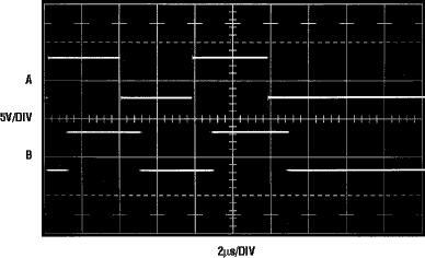
Figure 2. Positive-going double pulse behavior: A = driver input, B = receiver output |
Figure 3. Negative-going double pulse behavior: A = driver input, B = receiver output | ||
Figure 4. Driver in fast slew mode, loaded with 5000' of twice-terminated twisted pair |
Figure 5. Driver in slow slew mode, loaded with 5000' of twice-terminated twisted pair |
|
Figure 4 shows the driver output waveform when loaded by 5000' of terminated cable, operating in the fast slew mode (SLEW pin pulled high). The effect of the SLEW pin on the driver output waveform is noticeable in Figure 5, where rise and fall times of approximately 1µs result. |
|
Isolation can bring potentially dangerous voltages onto a circuit
board and within easy reach of the end user. For example, if the twisted pair
is accidentally miswired or faults to 117V at some remote location, the
floating section of each LTC1535 and its associated circuitry will also carry
117V. An unwary user or installer could then come in contact with what
is assumed to be a safe, low voltage circuit. Figure 6 shows how to
detect and warn the user that a fault condition exists on the twisted pair or
its shield. A small (3.2mm) glow lamp is connected between GND2
(the LTC1535's floating ground) and the equipment's safety "earth" ground.
If a potential of more than 75VAC is present on the twisted pair or
shield, B1 will light, indicating a wiring fault. Resistors R3 and R4 are used to
ballast the current in B1. Two resistors are necessary because each
resistor can only stand off 200V, as well as for reasons of power dissipation.
As shown, the circuit can withstand a direct fault to a 440V,
three-phase system.
Other problems introduced by floating the twisted pair include
the collection of static charge on the cable and
the attached circuitry. R1 and R2 provide a path to shunt static charge safely
to ground. Again, two resistors are necessary to withstand high
voltage faults. Electrostatic spikes and transients can temporarily elevate
the twisted pair to 10kV or more. C1 in Figure 6 absorbs this charge
and limits the peak voltage that reaches the LTC1535 to a safe value. For example, if a 1000pF source charged to 10kV comes in contact with
the cable, a single 10nF capacitor at C1 will reduce the peak voltage to
just 1kV, decaying in less than 10ms through R1R4 and B1. 1kV is
well within the capabilities of the LTC1535.
|
Figure 6. Detecting wiring faults |
|
Combining isolation, power, and a fully-compliant RS485 transmitter
and receiver, the LTC1535 provides a compact, cost-effective solution for
isolated serial data communications. |