
Figure 1. Output characteristic of Siemens SM6 solar panel at 1000W/m2 and 25°C

Design Idea:
|
Goran PericaIntroductionSolar panels are difficult to use as power sources for DC/DC
converters due to their output characteristics. Figure 1 shows a typical output
characteristic for a Siemens SM6 solar panel. Solar panels have almost
constant output current in their operating region (0V to 15V for the SM6).
They also have high output impedance in the operating region below the
peak power point, VPMAX (the SM6 has
10W to 500W output impedance for output voltages VSP <
VPMAX). Unfortunately, the output impedance is highest
during DC/DC converter start-up, when
VSP is below the peak output power point,
VPMAX, as shown in Figure 2. |
Figure 1. Output characteristic of Siemens SM6 solar panel at 1000W/m2 and 25°C |
Figure 1. Power output of Siemens SM6 solar panel at 1000W/m2 and 25°C |
|
A typical power source (a generator or a battery) will deliver more
power as the current drain increases. This is true in the region where the
load impedance is greater than the output impedance of the power source.
For the SM6, this happens in the region where
VSP is above VPMAX. In the
region below VPMAX, the power output starts decreasing as the current
drain increases. In other words, the panel is behaving as a current source
for output voltages below VPMAX and as
a voltage source for output voltages above
VPMAX.
When a DC/DC converter is connected to a solar panel, the
start-up inrush current caused by the converter's negative impedance
may exceed the peak current rating of the panel, causing the panel output
voltage to collapse; this results in a permanent latch-up.
The circuit shown in Figure 3 overcomes this problem by controlling
the inrush current. Normally, a converter has a preset current limit; at
start-up, input current surges to its peak value while the converter is trying
to bring the output into regulation. Start-up can be even more difficult
because the output load may demand full power from the source while the
solar panel is still operating in the region below its
VPMAX point. Also, the load may have a substantial amount
of output filter capacitance that has to be charged, thus requiring
additional current from the input.

Figure 3. Solar panel DC/DC converterVendors of non-LTC components used in this application |
|
Start-up is not a problem if input source can deliver the additional power required to charge the output capacitors, as shown in Figure 4. The waveforms in Figure 4 show the start-up of the circuit in Figure 3, without the components that control the start-up current surge (capacitor CSS removed). As can be seen, the input current surges to the 2A current limit of U1, an LT1308 micropower DC/DC converter, until the output reaches the 5V regulation point (Trace 4). In this case, the peak input current is limited by the current limit of U1. |

Figure 4. Inrush current (trace 3, 1A/DIV) with low impedance,
|
||
|
If the input power source is current limited, as is the case with a solar panel, the DC/DC converter may latch up in an undervoltage condition, as shown in Figure 5. As soon as U1 starts running, the input current reaches the peak set by the current-limited input power source. In the case of Figure 5, the input power source current limit is set to 0.8A and the converter still won't start. Also, there is an overcurrent transient (time from 32ms to 36ms) caused by the energy stored in the output capacitor of the source power supply. |

Figure 5. Inrush current (trace 3, 1A/DIV) with power source
|
|
Under this condition, the input voltage (Trace 2) starts to collapse
as soon as the load current reaches the preset current limit of 0.8A. Once
the source supply's bypass capacitor is discharged and the input voltage
collapses to 1.3V, the converter is latched up and can't recover. The output
voltage under this condition settles to a value that depends on the load (3V
in this case). If an undervoltage lockout were used, the circuit would enter
a hiccup mode, trying to restart.
One way of solving this problem is to set the switch current
to a lower value and to use a larger solar panel.
The circuit in Figure 3 overcomes the start-up inrush current
problem by reducing the current limit during start-up. As soon as the output
voltage reaches the VBE voltage of Q2,
Q2 starts conducting and pulls down on U1's
VC pin. The current limit is now reduced to zero. As
CSS is being charged, Q2's collector current
decreases and the current limit of U1 increases slightly, causing the
output voltage to rise. This process will continue until the output
voltage reaches regulation and CSS is
fully charged. At that point, resistor R4 pulls the base of Q2 to ground,
removing Q2 from the circuit. The rise time of the output voltage is
dependent on CSS, Q2 and R4. Because
the base current of Q2 is very small with respect to the current through
resistor R4, the base current of Q4 can be neglected. The value of
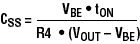
CSS required to raise the output from zero to
the nominal output voltage, VOUT, will be:
|
|
where VBE is the base-emitter threshold of Q4 and
tON is the desired turn-on time.
Start-up waveforms for the values in Figure 3's circuit are shown
in Figure 6. The input current exhibits only a slight surge,
reaching only169mA before settling to a steady-state value of 163mA .
|
|
The amount of output current that the LT1308 can generate also depends on the input voltage. The relationship between output current and input voltage is shown in Figure 7. |

Figure 6. Inrush current (trace 3, 1A/DIV) with power source limited to 0.35A and soft-start circuit |

Figure 7. Dependence of ouput current on LT1308's input volltage |
Inrush current control is a very desirable feature for converters
that use a solar panel as a power source. By preventing current transients
during start-up, the size of the solar panel can be kept to the
minimum required by the steady-state load. The circuit described here can be
used with any current mode control IC that has an accessible, high impedance
error amplifier output. In this fashion, a converter for solar
cell applications of any power level can be built. 