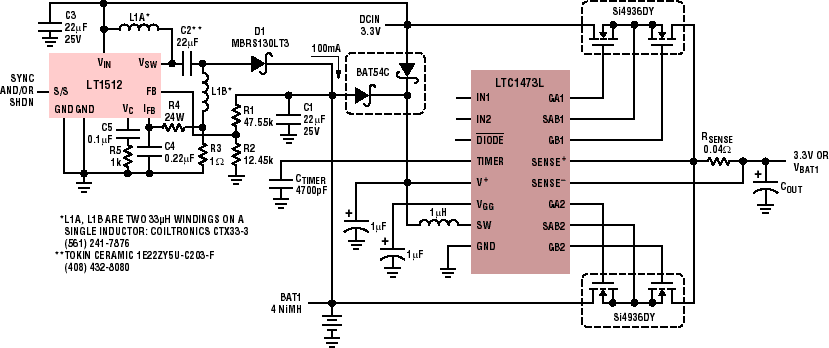
| by Peter Guan and Tim SkovmandThe LTC1473L solves the problem of seamless power switching between 3.3V or 5V supplies and back-up battery packs (3- or 4-cell NiMH) at high current levels. By driving two sets of back-to-back N-channel MOSFET switches, the LTC1473L routes power to the input of a low voltage (3.3V to 10V) system efficiently and inexpensively. An internal micropower boost regulator is included to fully enhance the external NMOS switches, even at low operating voltages.By using an external 1mH inductor and a 1µF capacitor, VGG is charged to approximately 8.5V above V+, providing ample drive for the external MOSFETs. The LTC1473L includes inrush-current limiting during supply switchover to produce smooth transitions between the DC supply and the battery backup and to ensure that the load capacitors are always charged and discharged in a controlled fashion.During start-up or abnormal operating conditions, when the two input voltages are varying, current can still be passed to the load from the high input source by enabling the /Diode pin, which essentially converts the two external MOSFETs into diodes. This "2-diode mode" is defeated when V+ drops below 2.5V.Continuous short-circuit proection is also provided by a programmable timer that limits the amount of time the switches are allowed to be in current limit. When the time limit is reached, the LTC1473L removes the gate drive and then retries the offending switch, at a very small duty cycle, until the short circuit is removed, thus limiting the power dissipation to safe levels. The LTC1473L is housed in a space-efficient 16-pin narrow SSOP package and drives a wide range of N-channel MOSFET switches.Figure 1 is a schematic diagram of an automatic PowerPathTM switch for 3.3V applications. The LTC1442 micropower, low voltage comparator monitors the DC supply rail with its internal 1.182V reference and an external resistor divider. As soon as the supply falls below 3V, the two comparator outputs change state and invert the two logic inputs (IN1 and IN2) of the LTC1473L. This action smoothly switches the load from the DC supply to the backup battery pack. For hysteresis on the comparator's trip point, an additional resistor divider can be added between the REF (6), HYST (5), and V (2) pins of the LTC1442 (refer to the LTC1442 Data Sheet for details). | |