This page has some basic thoughts (not rigorously analyzed) on EMI produced by a Tesla Coil
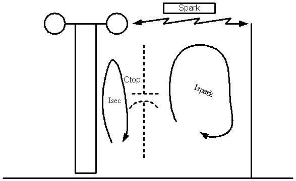
I assumed a TC that has a 50 pF top load, resonating at 100 kHz (Lsec = 50 mH), with a peak voltage on the top load of 500 kV. This works out to 6.5 Joules. The peak current in the secondary is about 16 Amps.
I further assumed that the TC discharges by means of a spark 2 meters long to a ground 2 meters away, and that the entire 6.5 J is dissipated in the spark in one shot. I assumed a nominal inductance for the spark and ground path of 4 microhenries (1 uH/meter is a reasonable number for a single wire...).

Ignoring loss in the spark, you can consider it as a LC circuit, which, given the 50 pF and 4 uH, resonates at around 11 MHz, that is, the spark rise time will be around 20-25 nsec (1 quarter cycle). Calculating the current in the discharge by L*I^2 = C*V^2, you get a peak current of about 1770 Amp
Now, look at the radiated electric field, at a distance of, say, 10 meters. A basic equation for the field due to a current in a conductor is E = 120 * pi * I * length / ( dist * wavelength), which gives the field strength (V/meter) with the current of I amps, length of the radiator is length meters, and the distance away is in meters.
First, let's calculate for the field due to the current in the secondary (16A). The wavelength at 100 kHz is 3000 meters, and running all the numbers gives you a field strength of 0.4 V/m at a distance of 10 m(tesla coils make terrible antennas...)
What's more interesting, though, is the field strength due to the spark discharge. Two factors are important: 1) The current is a LOT higher (100 times as much, in fact); and 2) the frequency is higher, which makes the wavelength shorter (11 MHz = 26 meters). Now, running the numbers gives you a electric field strength of 5130 V/meter, more than 10,000 times that of the field due to the current in the secondary.
This is more than 80 dB difference! Clearly, your coil is going to interfere worse when it is breaking out and making big sparks.
Now, let's calculate the voltage induced in some "victim loop". The general equation for the voltage across the terminals of a loop (or, actually, all the way around the loop) is: V = 2 * pi * Area * Nturns * E * cos(theta)/ wavelength where Area is the area of the loop in square meters, Nturns is the number of turns in the loop, E is the field strength in V/meter, theta is the orientation of the loop relative to the E field orientation (assume cos(theta)=1 for worst case), and wavelength is in meters, too..
Fortunately, the area of the victim loop is usually quite small (for instance, what's the area between the two wires in a piece of power cord... not much). But, let's say you have inadvertently hooked up your computer so that you have a nice loop. Perhaps you have an external modem, so the loop goes something like,from the outlet ground pin, up the power cord to the PC, from the PC to the modem along the RS232 cable, from the modem to the wall wart, and finally, maybe, back to the outlet. (I'm ignoring other potential loops here, like the phone cord itself, etc.) . It would be easy to get, say a square meter (just to make the numbers easy).
What's the voltage: 2 * 3.1415 * 1 * 1 turn * 5000 V/meter * 1/ 26 meters a mere 1200 V....
Now.. that voltage will be distributed all the way around the loop, and will distribute in proportion to the series impedances at 11 MHz. Obviously, the voltage drop along the wires will be pretty low (although.. you have to watch out for the inductance... 1 uH at 11 MHz is about 70 ohms). Most of the voltage will be developed across the various isolation components in the system (power supply transformers, etc.) which look like capacitors. Hopefully, the power supply transformer has a very small capacitance (so the impedance is high, and the voltage is high across it, because it is designed for 2500V breakdown, typically). 10 pF at 11 Mhz is 1.44 kOhm. Let's assume that 10 pF for each power supply (one in the PC and one in the wall wart). Let's further assume we have 4 meters of power and data cables.. There's probably also a couple hundred ohms between the RS232 line and ground in the driver circuits, etc. So, our total loop has a resistance of 2*1440 + 4 * 70 + 200 or, 3360 ohms total. Of the total 1200V, about 70 volts will appear across that 200 ohms in the RS232 driver... Result? Fried circuit...
note also that putting some sort of surge suppressor in the circuit might not help.. why? because the ground from the suppressor might itself form a loop.
The net result is that it is remarkably easy to cook stuff with long sparks (as those of you fooling with Marx banks have found, particularly small ones, which have very fast rise times..)
Basic techniques:
Note also that if you do a true "single point ground" system (bearing in mind that power distribution works as a ground wire, capacitively coupled), you can't get loops....
Copyright 2001, Jim Lux / tcemi.htm / 5 March 2001\ / Back to HV Home / Back to home page / Mail to Jim