INFOSEC Engineering
by
Dr. Bruce C. Gabrielson NCE
Basic Communications Theory
Chapter 1
Communicating Information
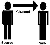
Communications occurs when information is transmitted or sent between an information source and the user of that information.
For information to get from one place to another, there must be a transmission medium or channel between the source and receptor (information sink). The three parts, source, channel, and sink
(shown in Figure 1) represent the entire information system.
When information is put into a language understood by machines it becomes data. Data transmission occurs when data is moved electronically between two points. The resulting electronic information system can be a telemetry system, computer/digital system, or telecommunications system.
Machines can deal with two types of electronic information, analog and digital. An analog signal is a continuously varying voltage waveform made up of various frequencies. A frequency is the number of times a sinusoidal waveform repeats during a one second interval (cycles per second). When all of the individual frequencies making up a waveform are combined, the resulting signal can appear in numerous ways.
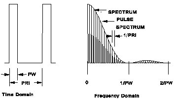 A digital rectangular signal also made up of analog waveforms located at specific frequencies as shown in Figure 2.
The squarewave is made up of a fundamental frequency, plus a number of odd harmonics, 3rd, 5th, 7th, etc. The higher harmonics contribute to the steepness of the rising and falling edge of the waveform, and also result in greater bandwidth needs for the communications channel. However, regardless of components of the digital signal, the resulting combined waveform is dominated by two principal states, high or 1 and low or 0.
A digital rectangular signal also made up of analog waveforms located at specific frequencies as shown in Figure 2.
The squarewave is made up of a fundamental frequency, plus a number of odd harmonics, 3rd, 5th, 7th, etc. The higher harmonics contribute to the steepness of the rising and falling edge of the waveform, and also result in greater bandwidth needs for the communications channel. However, regardless of components of the digital signal, the resulting combined waveform is dominated by two principal states, high or 1 and low or 0.
Electronic waves propagate near the speed of light. When the communications medium is air, there is little impedance to prevent a particular pulse shape from reaching its destination in the same configuration as when it was transmitted.
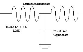 A problem occures when the medium is not air (or optical fiber), but a hardwire cable. Wires contain distributed inductance and capacitance (Figure 3), which causes some of the initial pulse frequencies (all at a certain phase) to reach their destination slightly out of phase with respect to the other frequencies. Waveform distortion occures when these signals do not accurately represent the original waveform. Fortunately, in digital transmission systems, less care is needed to maintain the proper positions of the combined signal since the digital waveform (squarewave) can be regenerated when it becomes distorted.
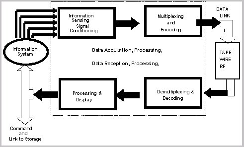
A sample telemetry system is shown in Figure 4. Notice in this case a sensor converts physical motion into analog electrical energy. For transmission, the analog signal is encoded to create a digital waveform.
Once the information has been formatted in an analog or digital form, it needs to travel across a channel. If the signal is in digital pulses, and the channel is a wire or fiber optic cable, transmission can take place directly. If the channel is a telephone network, the digital signal must be converted to an analog (voice-like) signal using a modem. The common carrier system carries the majority of telecommunications (voice and data) information.
Modulation
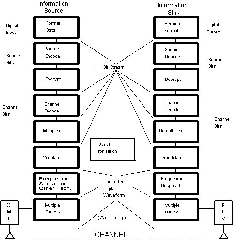
For a digital transmission system, the information source can be digital data, or analog data converted to digital form. A typical digital communication system is shown in Figure 5. The upper blocks of the figure indicate signal transformation from the source to the transmitter and the lower blocks illustrate signal transformations from the receiver to the sink. Notice that the data channel is easily encrypted and decrypted near to the digital information source.
If the channel is air, the formatted information must be further manipulated into a voltage form at some specified frequency so it can be easily transmitted from one point to another. In this case, the digital pulses or the sensor voltage, called the signal, must be attached to or superimposed on other voltages at frequencies that move easier in the transmission medium. The process of attaching signals to other easier to propagate signals (carriers) is called modulation.
A carrier is a wave having at least one characteristic that may be varied from a known reference value by modulation. The carrier frequency, fc, is normally the frequency to which a receiver is tuned in order to extract modulation. In broadcast communications, fc is much higher than the modulation frequency, fm. This, however, may not always be true as in the case of power line communications where fm > fc.
Transmission bandwidth refers to the frequency range over which signals can be transmitted without significant loss of energy. Carriers are known frequencies that can be readily detected using a narrow bandwidth receiver tuned to the transmitted signal. When the transmission medium is a wire, the bandwidth in bits per second refers to the wires signal carrying capacity. Some types of communications systems exist that utilize very wide bandwidth receivers and unique modulation techniques, but these will not be discussed here.
Modulation is the process by which some characteristic of a carrier is varied in accordance with a modulating wave. Complex modulation is any combination of modulation techniques applied to a single carrier. It may be achieved by imposing multiple modulation techniques on a single carrier, as in quadrature phase shift keying - amplitude modulation (QPSKAM) and the use of the FM carrier for both the FM modulation and the subsidiary communication authorization (SCA) modulation, or by using a succession of modulated carriers to modulate a higher level carrier, as in Bell System frequency domain multiplexing (FDM). Unintentional complex modulation is also frequently the result of poor filtering and unintended feedback loops.
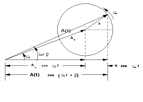
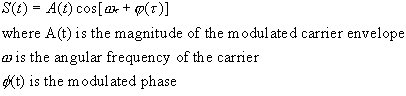
Figure 6 is a vectorial representation of an instantaneous modulated signal. Mathematically, this signal is described by:
As discussed below, there are three ways the carrier can be modulated: amplitude (AM), frequency (FM), and phase (PM). In addition, any combination of modulation techniques can be applied to a single carrier. Complex modulation may be achieved by imposing multiple modulation techniques on a single carrier, as in quadrature phase shift keying - amplitude modulation (QPSKAM) and the use of the FM carrier for both the FM modulation and the subsidiary communication authorization (SCA) modulation, or by using a succession of modulated carriers to modulate a higher level carrier, as in Bell System frequency domain multiplexing (FDM).
Unintentional complex modulation is also frequently the result of poor filtering and unintended feedback loops.
Angle modulation is accomplished in two forms:
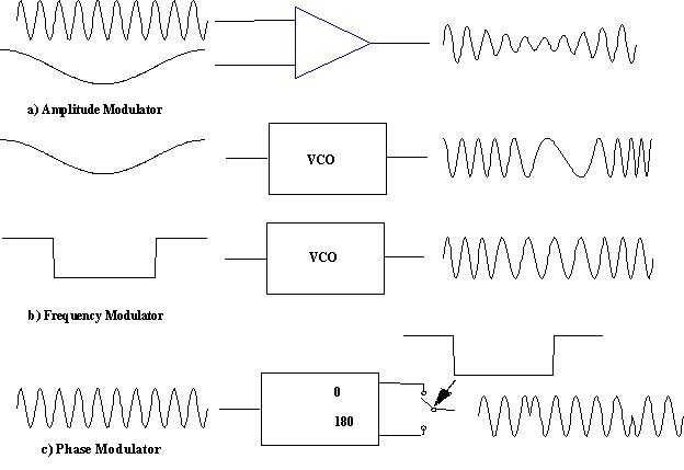
Figure 7 compares AM, FM, and PM for simple analog and digital modulating signals. Note that for analog modulating signals, the difference between FM and PM is essentially a phase shift of the modulator. For digital modulators, however, the resulting FM and PM signals are extremely different, as will be demonstrated below.
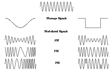
Figure 8 illustrates simple, "natural," techniques for accomplishing each type of modulation. Note that both AM, FM, and analog PM can occur easily in normal circuits using amplifiers and oscillators. Digital PM is much more difficult to generate and almost never occurs unintentionally.
Spread Spectrum
One other non-traditional modulation technique should be mentioned in passing. Spread Spectrum is a modulation technique for multiple access, or for increasing immunity to noise and interference. It is also used to reduce the probability of intercept to safeguard communications and radar.
Spread spectrum basically combines the analog signal with a pseudorandom digital bit stream. The resulting signal resembles wideband Gausian characistics similar to white noise.
Digital Amplitude (Pulse) Modulation
Since computers understand digital signals rather than analog signals, modulation techniques were developed which lend themselves to digital processing. Digital AM is a special case of linear AM in which the instantaneous amplitude, x(t), is constrained to a finite number of discrete values. Common examples of digital AM are simple pulse modulation, On-Off Keying (OOK), and amplitude shift keying (ASK). Pulse modulation and OOK normally only use two amplitude states, carrier off and carrier on, and data bits are transmitted serially. In theory ASK can have any number of amplitude states, but practical applications normally limit ASK to no more than three states: high, or positive (+); zero (0); and low, or negative (-). Tri-state ASK is frequently used in systems which employ return-to-zero (RZ) coding schemes.
Referring back to Figure 2, the figure showed both the time domain and frequency domain (spectrum) representations of a rectangular pulse train. (The spectrum shown is the first two positive frequency lobes of a characteristic power spectrum. Lobes similar to that between 1/PW and 2/PW, with continuously decreasing amplitude, are repeated infinitely. The negative frequency portion of the spectrum is the mirror image of that shown.) The spectrum and the pulse train have several characteristic features:
Pulse Repetition Rate (PRR), (also pulse repetition frequency [PRF]) -- the number of pulses transmitted in one second. This frequency represents the frequency separation between the discrete spectral lines in the pulse spectrum and is the maximum spectrum analyzer or FSVM bandwidth (BW) at which one can view the line spectrum. When viewing line spectra, the peak level for each line is a true indication of all the power at that frequency. Any BW greater than PRF will always contain more than one spectral line, thus generating a continuous curve, or pulse spectrum. The peak level displayed for pulse spectra is a function of the number of lines contained within the receiver BW and not a true representation of the pulse power. (Interpretation of pulse spectra is beyond the scope of this paper.) The time from the start of one pulse to the start of the next pulse is the pulse repetition interval (PRI), PRI = 1/PRF = t.
Pulse Width (PW, T) -- the length of time the pulse is ON. The frequency described by the inverse pulse width (1/PW) is the frequency distance between spectral nulls. This is the maximum BW which will show the lobe structure of the pulse (the pulse spectrum). The main lobe of the spectrum is 2/PW wide with its peak at fc (0 Hz if the pulse is not modulating a carrier). This is the minimum receiver BW for accurate demodulation of the pulse. Since more than 90% of the pulse power is contained within the main lobe, the peak level indicated at approximately 2/PW is a good indication of the power in the pulse.
 Pulse modulation techniques vary depending on the data processing technique being applied. Pulse modulation systems sample the input sinewave to yield a close approximation of the original analog waveform.
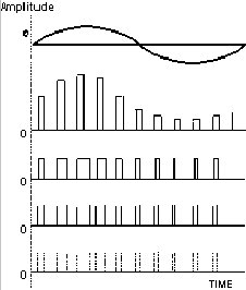
Figure 9 shows the four primary means of pulse modulating an analog signal.
Pulse modulation techniques vary depending on the data processing technique being applied. Pulse modulation systems sample the input sinewave to yield a close approximation of the original analog waveform.
Figure 9 shows the four primary means of pulse modulating an analog signal.
The second row of the figure shows a direct modulation of the analog signal. This technique, called pulse amplitude modulation (PAM), is seldom used since voltage amplitudes are degraded by noise. To prevent degradation when the digital signal is re-composed, constant amplitude pulses are normally used.
The third row of the figure shows pulse duration modulation (PDM). PDM carries the information in the pulse width, which varies with the amplitude of the signal at the sampling time. If this waveform is differentiated, then rectified, the pulse position modulation (PPM) shown in row four results. The distance between two pulses represents the sampled amplitude of the analog signal, with the first pulse as the zero time reference. Average system power for PPM is much lower than that required for PDM. but at the expense of greater bandwidth.
Both PPM and PDM use constant-amplitude pulses, but are still analog representations of the analog signal. To improve system performance, pulse code modulation (PCM) was developed. In PCM (row five) the sampled value is converted to a binary code which can be used directly by a digital computer without further processing.
Multplexing
Transmission over wirelines can occur in one or both directions at the same time. A simplex circuit allows one direction of information between source and sink. Half-duplex systems can send and receive information, but can only be used in one direction at a time. In a full-duplex system, transmissions can occur in both directions simultaneously.
Obviously, a communication channel would be inefficient if it only carried one data stream or one analog sensor output at a time. To increase efficiency, data multiplexing techniques have been developed that allow the combination or compression of several channels of information into one communications channel.
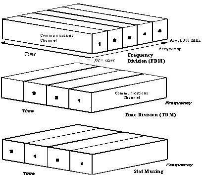 Figure 10 indicates the difference between the various techniques employed in data multiplexing. The front surface of the half cone represents the total frequency available in a communications channel (a telephone circuit in this case). The length represents that bandwidth as a function of time. In Frequency Division Multiplexing (FDM), specific chunks of bandwidth carry each channel's data. In Time Division Multiplexing (TDM), time slices of the whole bandwidth carry each channel's data sequentially with all channels repeated in sequence. Finally, in Stat Muxing, only the channels with data use a time slice to transmit their information. Thus, channels with higher volumes of information get more opportunity to send data.
Coding
Although digital and analog signals can be propagated continuously, in the real world messages from a computer based system are normally combined with other massages and then sent in packets of information. Codes are used to make up this packeted message format for information exchanges. Digital information is transmitted using codes consisting of 1's or 0's representing logical units. Each type of information designation, such as text, graphics, control characters, etc. has a separate bit pattern.
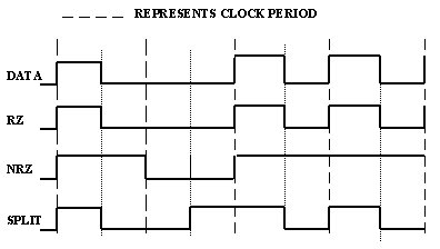 PCM coding, return-to-zero (RZ), non-return-to-zero (NRZ), and split-phase are the three common methods of coding in pulse modulation systems. The RZ format is standard, easy for both coding and decoding. The NRZ format requires, on the average, half the bandwidth (or twice the data rate) of RZ. When accuracy is the prime criterion, Manchester split-phase format is used. Manchester coded data is easier to synchronize because there is one transition from high to low (or from low to high) for each bit.
The three coding techniques for a simple data signal are shown in Figure 11.
PCM coding, return-to-zero (RZ), non-return-to-zero (NRZ), and split-phase are the three common methods of coding in pulse modulation systems. The RZ format is standard, easy for both coding and decoding. The NRZ format requires, on the average, half the bandwidth (or twice the data rate) of RZ. When accuracy is the prime criterion, Manchester split-phase format is used. Manchester coded data is easier to synchronize because there is one transition from high to low (or from low to high) for each bit.
The three coding techniques for a simple data signal are shown in Figure 11.
Propagation
Once the information has been properly packaged (packets combined, multiplexed and modulated) for transmission, the resulting signal is ready to be sent through the air or over the transmission line. This process is called propagation. Propagation results when a modulated signal is impedance matched to the air (or transmission line) at a specific frequency. Impedance matching means that there is virtually no resistance between the energy in the signal and the medium where the signal is going. All wires have a characteristic impedance associated with their distributed inductance, capacitance, and resistance. Air has a characteristic impedance of 377 ohms.
Antennas are designed to minimize the impedance mismatch between the signal source and air. If the transmission medium is a wire, and if the wire is not properly impedance matched, a fault or abrupt change in impedance will occur at the load end. This abrupt change in impedance causes the signal to partially reflect back down the wire, and also to create a power loss by partially radiating into the air.
The problem with impedance mismatch is also the reason for unintended noise transmissions. The basic premise is that energy is always conserved. In other words, if the total energy cannot be absorbed by the load or re-absorbed by the source, then it must end up radiating into its environment.
 The bit energy states for two signal types (RZ and NRZ)
are shown in Figure 12.
A digital squarewave is composed of voltages at many different frequencies, nearly all of which appear during the rising or falling edge of the waveform. Regardless of electronic circuitry and transmission line involved, at some frequency the transmission line will not be impedance matched. Therefore, the excess energy that will not be absorbed into the load or source will always be transmitted. Obviously, this energy is directly related to the digital signal.
The bit energy states for two signal types (RZ and NRZ)
are shown in Figure 12.
A digital squarewave is composed of voltages at many different frequencies, nearly all of which appear during the rising or falling edge of the waveform. Regardless of electronic circuitry and transmission line involved, at some frequency the transmission line will not be impedance matched. Therefore, the excess energy that will not be absorbed into the load or source will always be transmitted. Obviously, this energy is directly related to the digital signal.
Simple Data Exchanges
Regardless of the physics involved in getting information from point to another, comprehension by the receiver is necessary. Simply reversing the steps taken to send the information over a channel is not enough to ensure comprehension takes place. For a simple information exchange to work, the interface, code, protocol, and synchronization must be compatible.
A compatible interface means that the receiver must also use the same air, wireline, or optical channel as the sender is using. If the channel is a wireline, the information must be sent over a serial or parallel interface using some type of encoded digital pulse streem that follows an industry standard.
The industry standard for signal and cable formats that connect data terminal equipment and data communications equipment using a serial binary encoded data stream is EIA RS-232. There are also other standards for communications channels such as ISDN in the telecommunications industry and CCITT standards for FAX equipment.
Digital Communication Protocols
A protocol is a collection of rules and conventions for correctly transferring information. Protocols may vary depending on the circumstances and equipment, and only when the same protocols are used can equipment successfully operate together. Protocols for digital communications comprise three areas: method of coding, method of transmission and reception, and the method of controlling information exchanges.
Protocols define message preparation, communications channel establishment, and communications management during transfer. As the message is prepared in a packet for transmission, an address is attached and, if the message is long, it may be split into smaller packets. The lower protocol rules make sure the other station is ready to receive the message, and then define how the transmission should be monitored by each station as it passes over the cable.
 There are several commonly used protocols for data transfers.
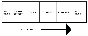
A simple protocol called High-Level Link Control (HDLC) (Figure 13) uses an 8-bit flag at the beginning of a transfer to tell the receiving device that data is going to be transmitted.
Address information next indicates the station where the information is being sent. Control bits keep track of how many frames were sent while frame check provides error control.
There are several commonly used protocols for data transfers.
A simple protocol called High-Level Link Control (HDLC) (Figure 13) uses an 8-bit flag at the beginning of a transfer to tell the receiving device that data is going to be transmitted.
Address information next indicates the station where the information is being sent. Control bits keep track of how many frames were sent while frame check provides error control.
TCP and IP are the two best known protocols used in the "Internet protocol suite". They are commonly used together as TCP/IP to describe the entire family of these protocols. TCP/IP is in reality a layered set of protocols used by cooperating computers to send commands, share resources, and otherwise communicate over a network. These protocols, which include TCP, IP and UDP, are used to provide the "low-level" functions necessary for many applications to work.
Synchronization
The final requirement for a formal communications channel to exist is the means of ensuring both transmitter and receiver are looking at the same information at the same time. This is done through the process of synchronization. A synchronized data transmission sends a series of characters across the information channel under a timing control sequence initiated at the transmitter. This clock must be in synchronization at both ends to avoid the loss of any data bits. These unique sync bits precede each data block so the receiver can be synchronized before the data start bit arrives.
In some communications channels, such as Ethernet, a clock stream is first sent over the channel so the receiver can prepare for and lock on to the pulses prior to data being sent. In a radio communications system, a phase lock loop circuit is sometimes used to sync the receiver to the transmitted signal. Other formats for synchronizing data transfers use a sequential sampling approach or time multiplexed formats previously described while still others use a token passing system.