View Laser Bounce Listening Device for additional notes and technical information of older devices.
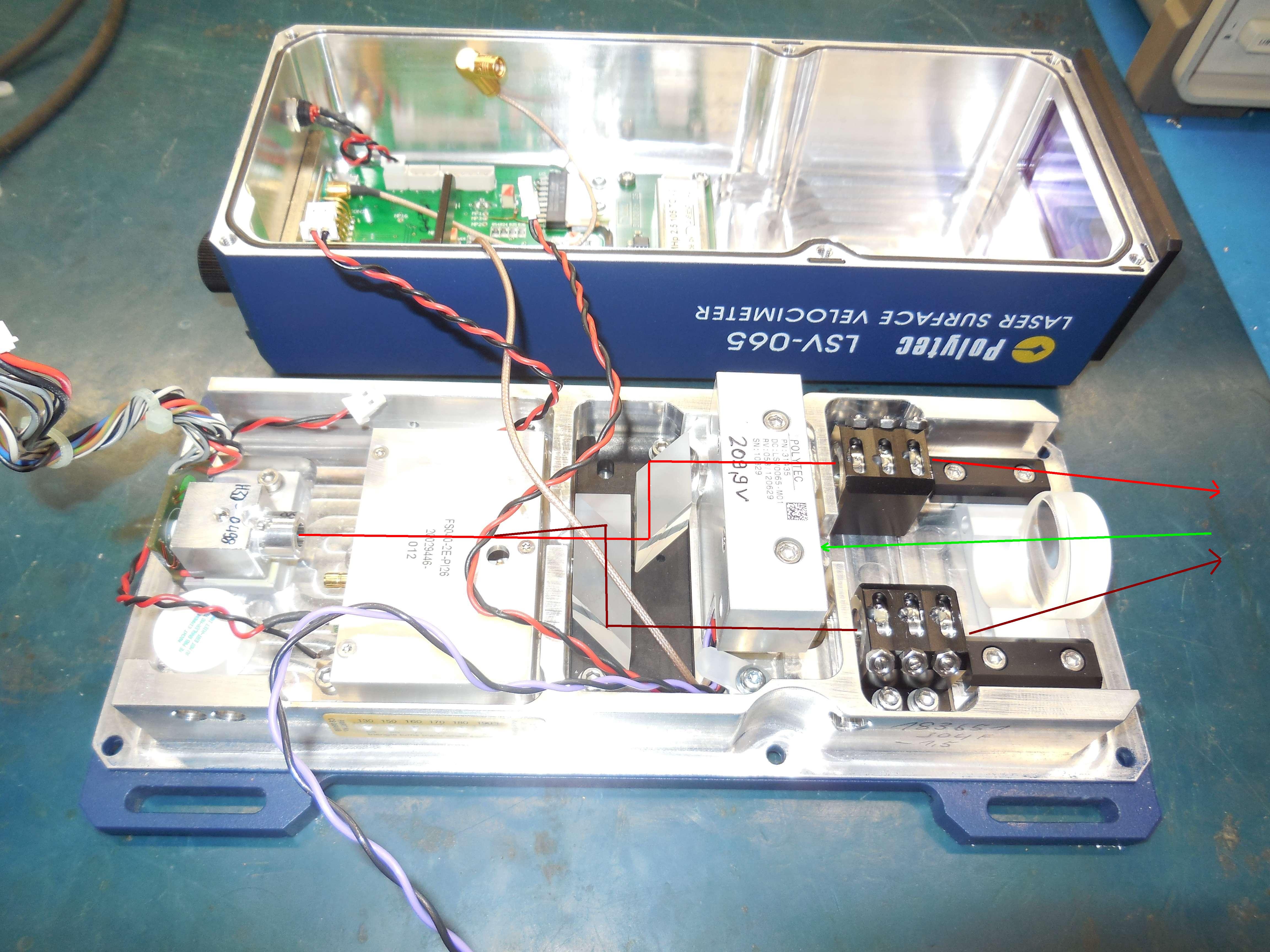
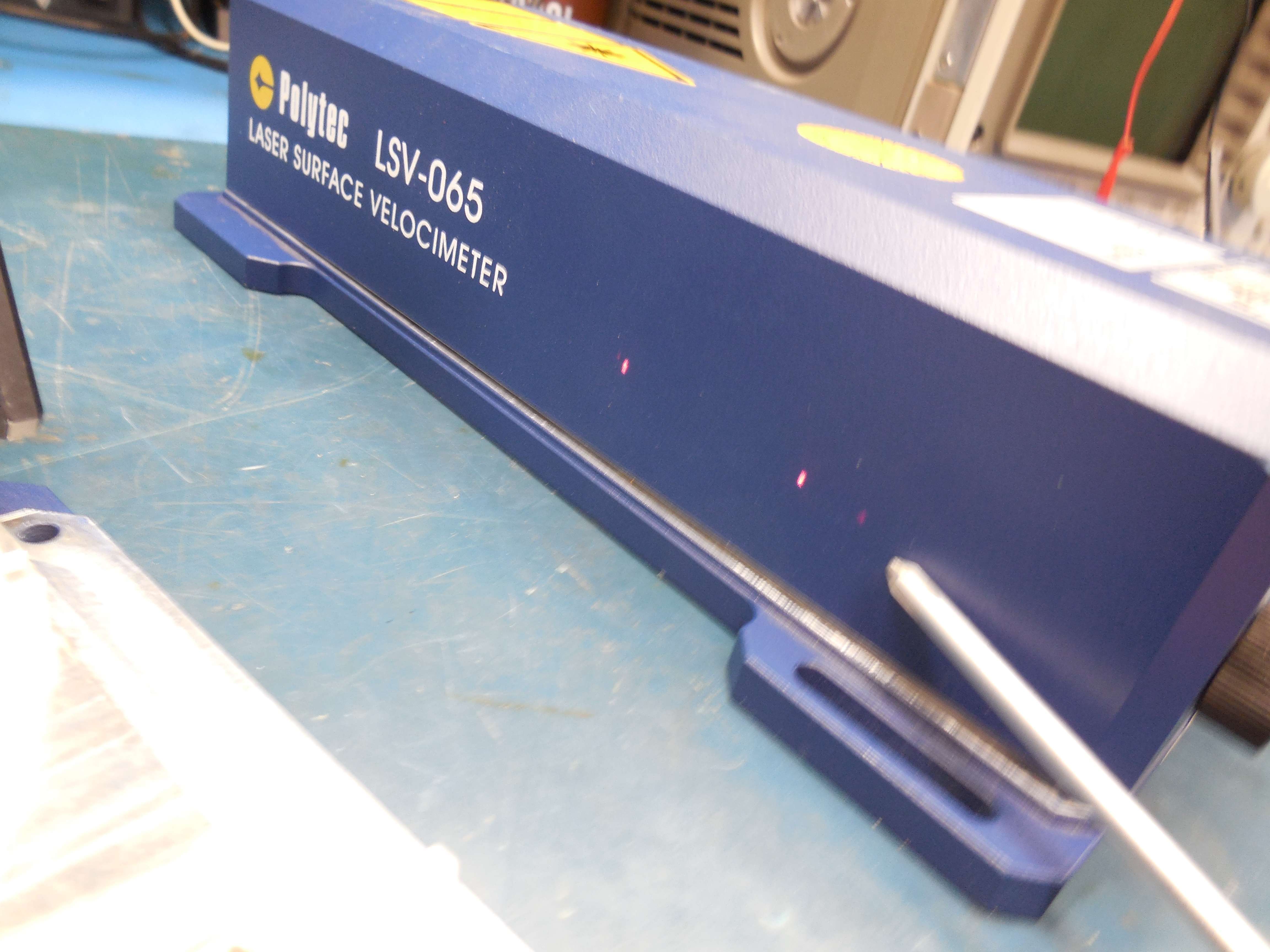
Internal view of a stock Polytec LSV-065 Laser Surface Velocimeter showing the laser beam paths.
The Peltier-cooled laser diode (670 nm) is on the left. Next is the Bragg modulator (+15 VDC) with an internal 40 MHz oscillator and divided-down 10 MHz oscillator reference output.
The Bragg modulator feeds a prism/beam splitter combination which splits the beam into an unmodulated (RED path) and modulated (BROWN path) beam.
The beam then leaves through steering optics. On receive, a centrally-mounted plano-convex lens focuses the reflected (GREEN) beam onto an avalanche PIN photodiode.
The target modulation is then imposed on this 40 MHz carrier and the output (50Ω) of the photodiode module is this signal which we'll need to demodulate:
- Doppler (velocity) = Fairly easy, standard FM discriminator.
- Phase (displacement) = Much more complicated, but the sensitivity is insane.
Here is a helpful Polytec PDF file titled Basic Principles of Velocimetry,
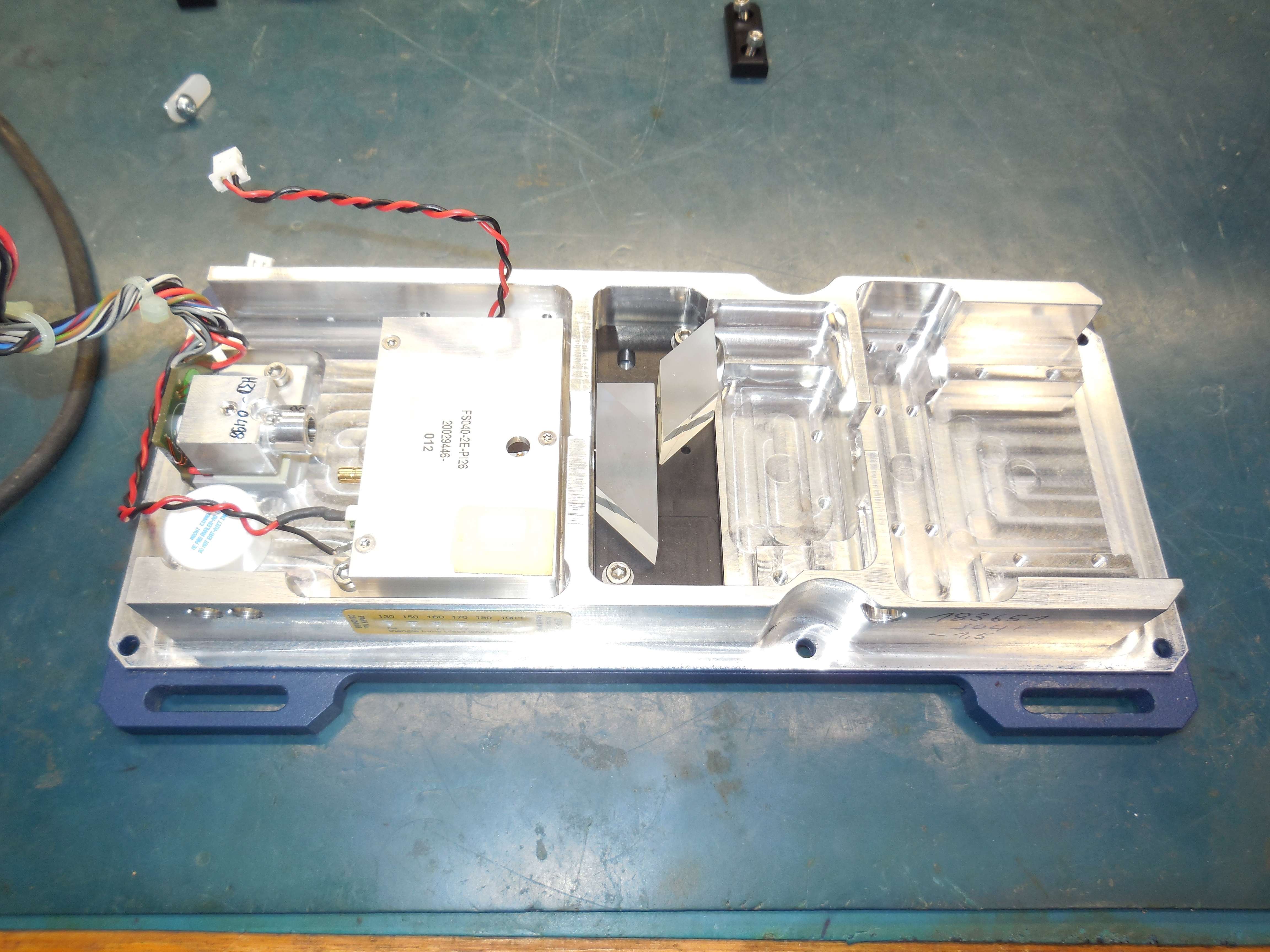
We'll need to remove the beam-steering optics, the receive optics, and the avalanche PIN photodiode module.
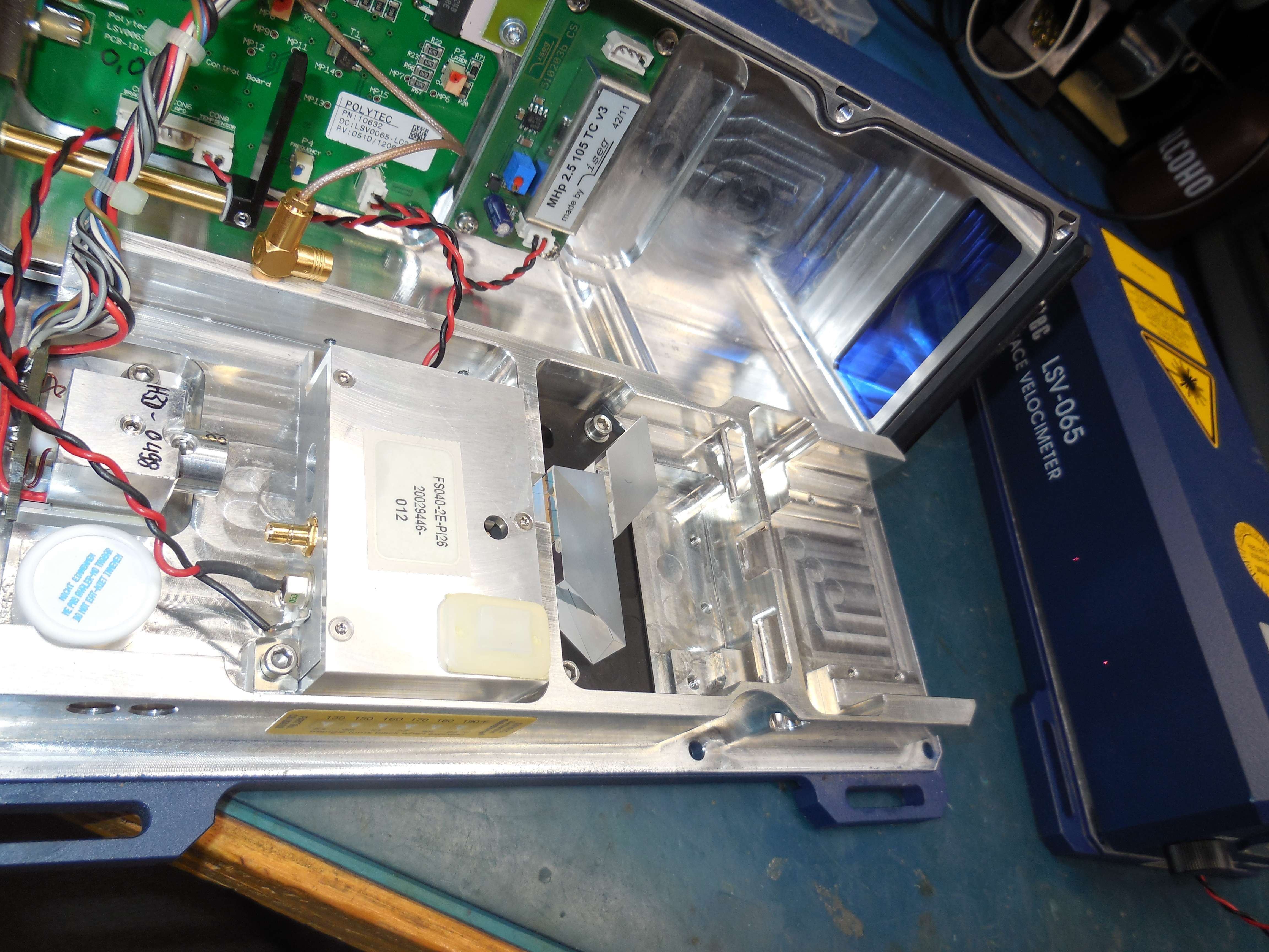
Alternate view with the front-end modules removed, but with proper power now applied. Go here for the DBM-17W2S connector pin-out.
Note the two little red dots on the right.
The top dot is the unmodulated reference beam.
The bottom dot is the 40 MHz modulated signal beam.
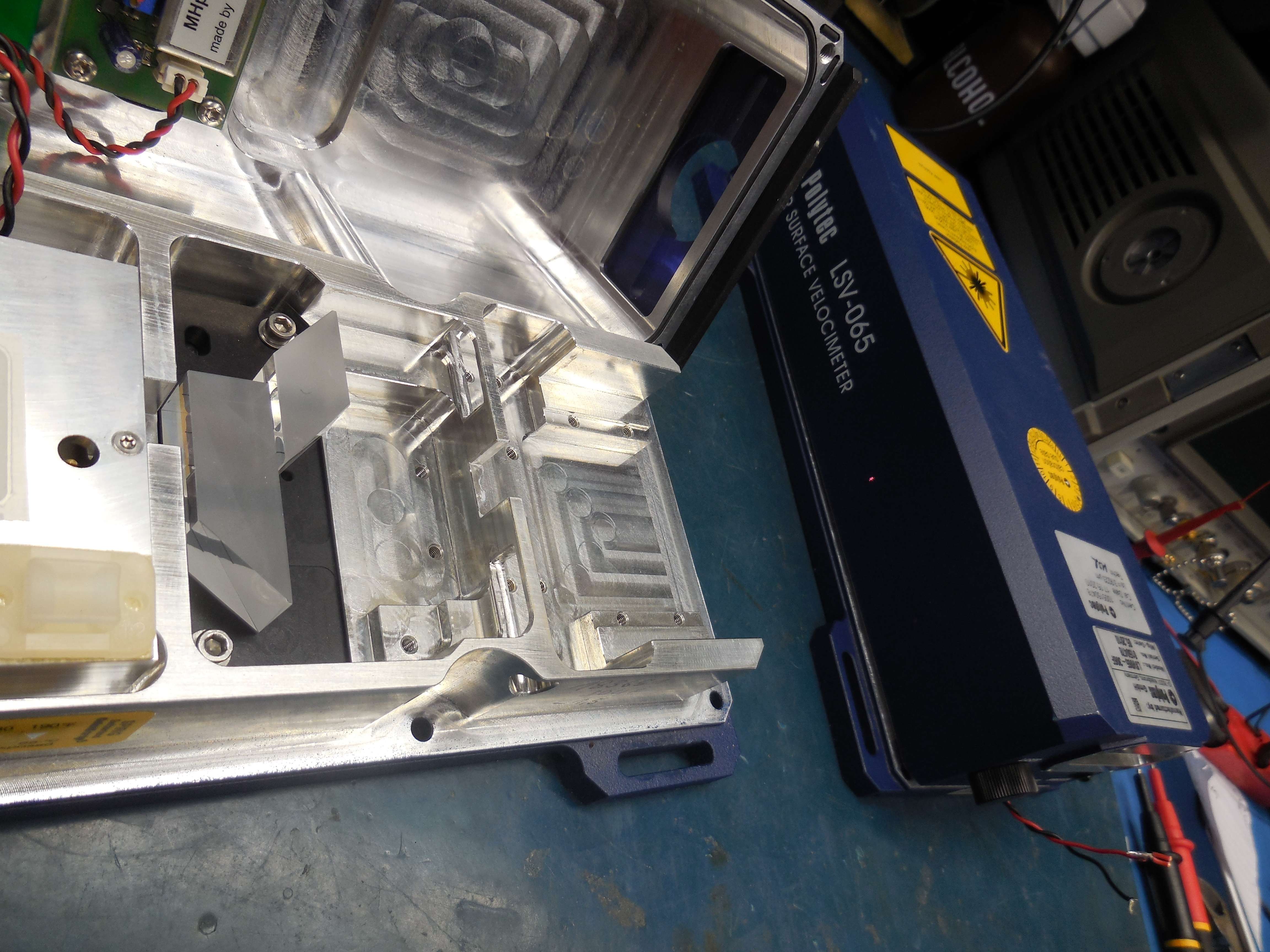
Alternate view with the front-end modules removed, but with proper power now applied.
The power (+15 VDC) to the Bragg modulator was removed, so only the unmodulated reference beam is output.

Close-up view of the output while the Bragg modulator was powered off.
The top dot is the unmodulated reference beam.
The bottom small dot is leakage from the Bragg modulator. This is called the "zeroth-order" modulation and is normal, but we should make note to applied stray beam capture material internally.
Close-up view with everything properly powered.
The top dot is the unmodulated reference beam.
The middle dot is the modulated signal beam.
The bottom dot is the stray "zeroth-order" modulation beam (near the screwdriver tip).
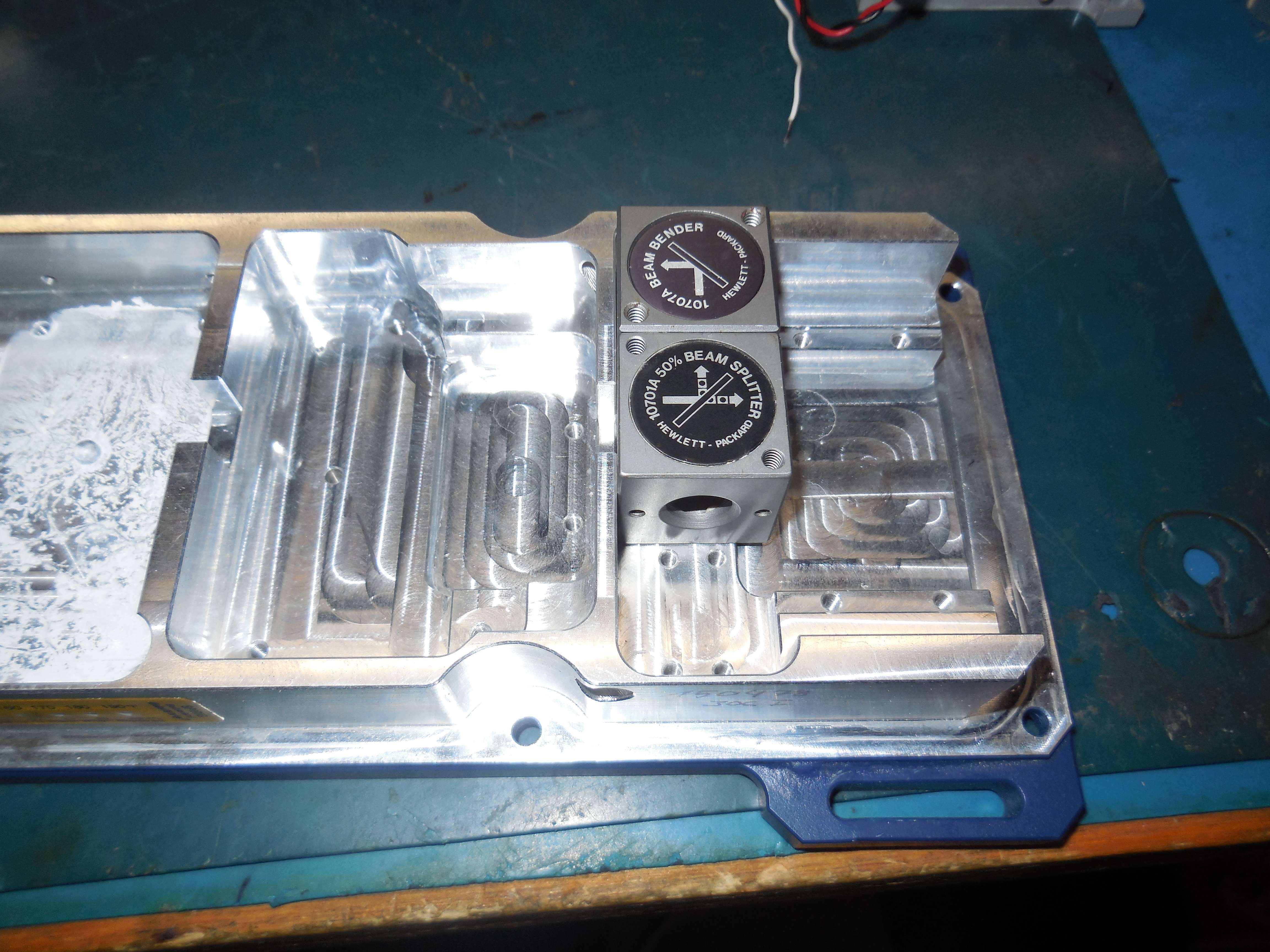
Referring to Figure 1 in the U.S. Patent 6.714,306, we'll need to add a beam bender and a beam splitter.
Shown here are a Hewlett-Packard 10707A Beam Bender and a Hewlett-Packard 10701A 50% Beam Splitter (just for fitting). The internals of the LSV-065 had to be milled out slightly to allow these optics to fit.
Other less-expensive optic modules will work, but these HP ones are much more convenient.
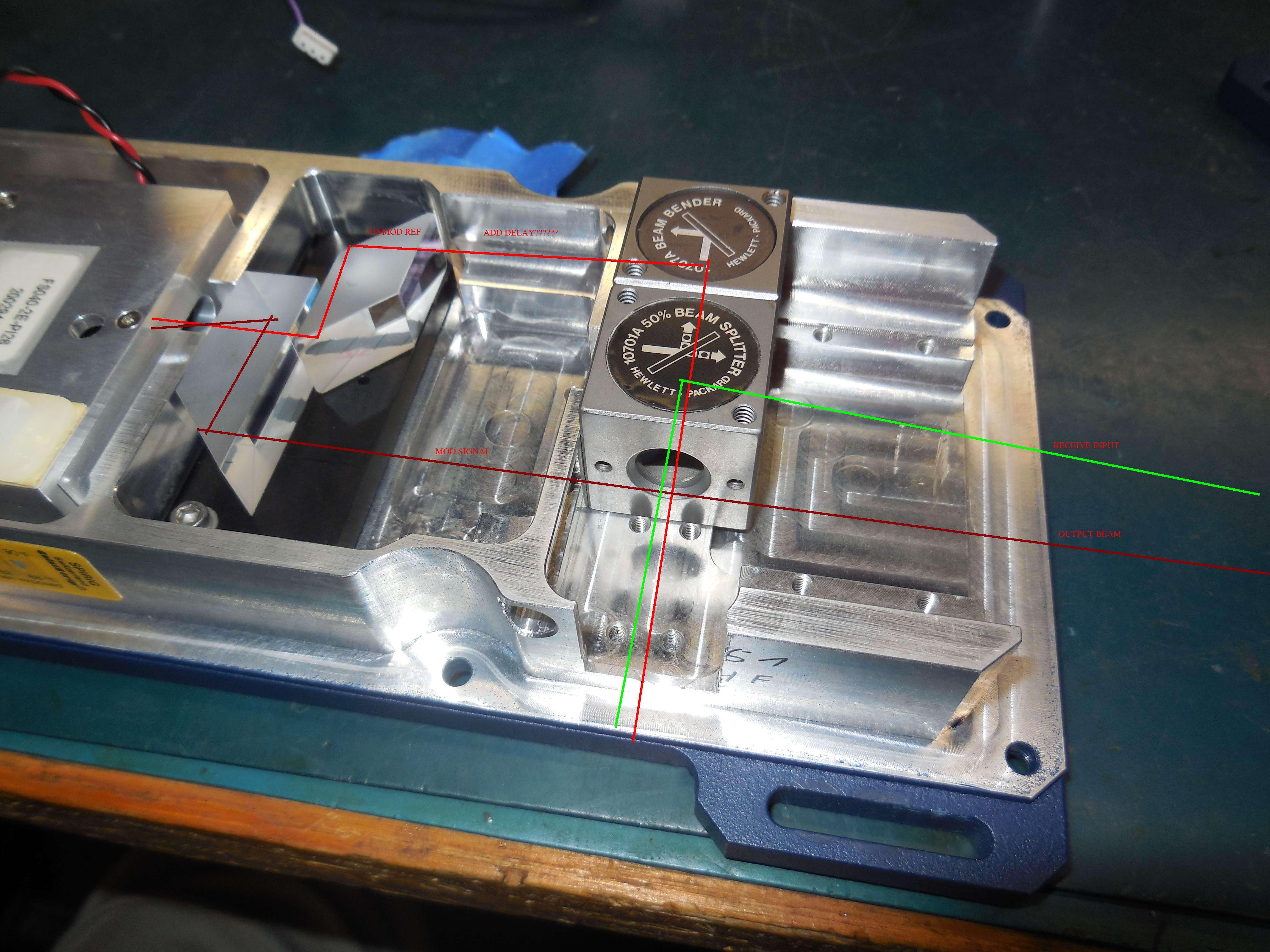
It seemed to work out well. I was going to just drill a hole for the receive laser output, but milled the side of the case instead.
I'm not sure what they mean with "an optical delay 21 equal to the delay encountered in the sampling process" in the patent. I know lasers can change their phase as the beam travels, so you technically need "both" beams the same length for proper phase demodulation.
I have no idea how to do that, so we'll just skip that step for now. LOL. (Optical Delay Notes)

Plans changed. No need to externally mount the photodetector. Turns out, you can still use the original PIN photodetector module location.

There is enough leeway with the original photodetector mounts to "slide" back-and-forth for proper line-up of the HP receive optics.

Alternate view.

Solder a extended PCB-mount SMA jack to the output coax on the photodetector module. This will be mounted to the top of the unit.
This is our 40 MHz modulation output jack.

Testing the optical line-ups. Note the red dot near the opening to the photodetector module. That's the unmodulated reference beam from the beam splitter. The photodetector module itself can slide left-and-right and those two Allen screws on top allow the internal PC board for the PIN photodiode to move (slightly) up-and-down.
The red dot on the lower-right is the output of the 40 MHz modulated target beam.
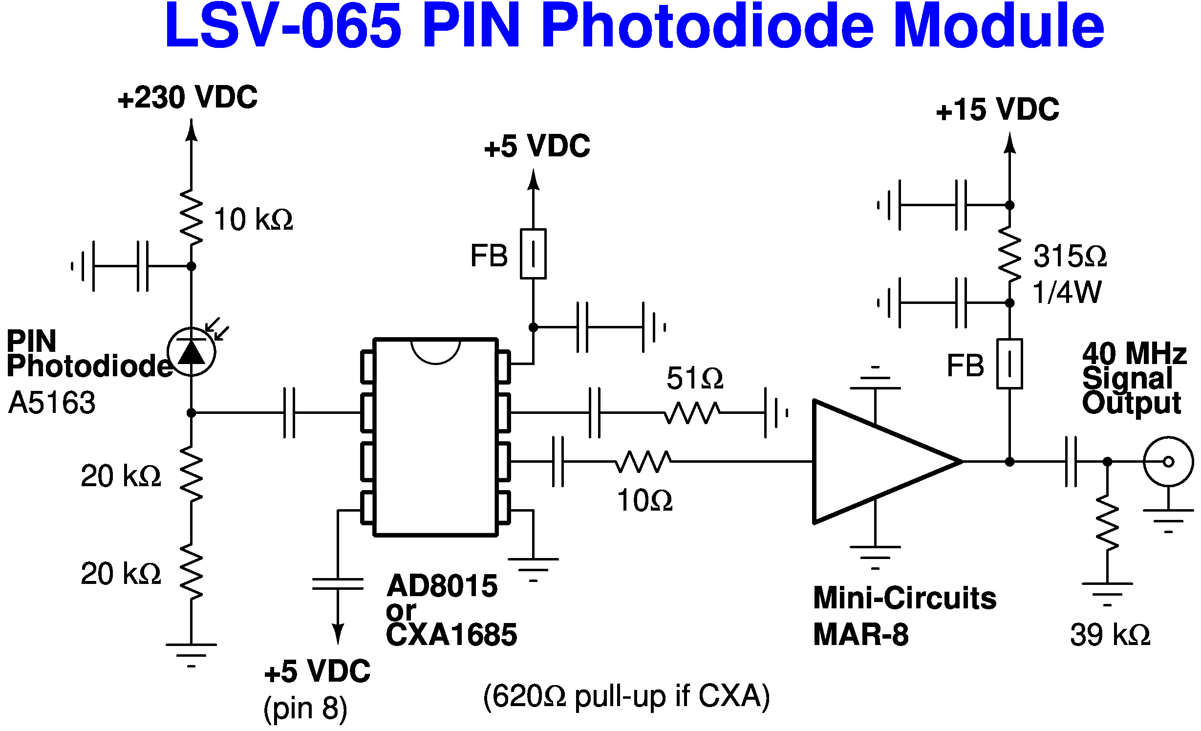
Partial schematic of the stock Polytec LSV-065 PIN photodiode receive module.
There appear to be at least two different designs, based around an Analog Devices AD8015 or Sony CXA1685 transimpedance amplifier. Both feed a Mini-Circuits MAR-8 amplifier for the final 40 MHz output.

We need to tap the 40 MHz oscillator Bragg oscillator signal. For some reason, the LSV-065 utilizes a divide-by-4 (10 MHz) on the oscillator tap. We'll need to bypass this.
Carefully remove the oscillator board by removing the two screws and unsoldering the connections.

Overview of the Bragg cell connections.
They are very delicate. Be careful!
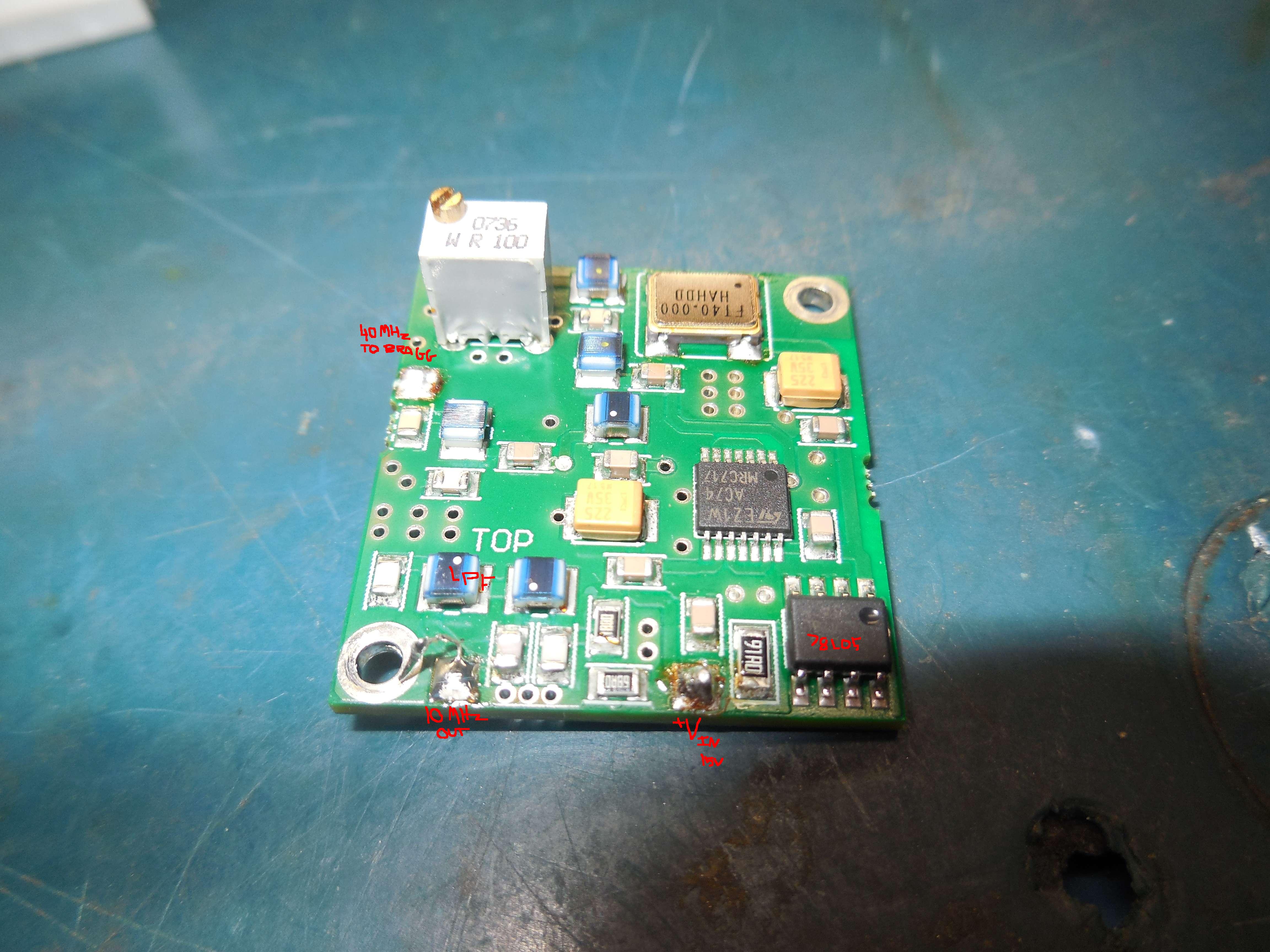
Overview of the stock oscillator board.
It contains a 40 MHz clock oscillator, 74AC74 configured for divide-by-4, a 5 VDC voltage regulator.
It requires +15 VDC input.

Rear view of the stock oscillator board.
The output transistor is BFG235.

Unsolder and remove the 74HC74.
Also unsolder and remove the output capacitor and inductor on the 10 MHz filter. See the exposed pads on the lower-left.

Tap a feed-through via going to pin 3 on the 74AC74 and connect it to the original 10 MHz output pad.
This will feed the 40 MHz clock oscillator output to this pad.

Putting it all back together.
We'll add an external amplifier and filter on the oscillator output.

This is the raw 40 MHz clock oscillator signal from our new output.

This is the filtered 40 MHz signal going to the Bragg cell.