We made a lot of very interesting basic research yesterday. The screen tests were very simple but effective, we found a number of harmonic frequencies where there was a strong signal, particularly at 83.7 MHz. This frequency gave a 3 db signal strength reading and the tonal changes relative to image change were very apparent.
The experiment didnt reach as far as recreating the image with a second monitor, and this will need a second experimental set-up. The problem in this set-up was that the monitors were quite sophisticated LCD monitors, this did not restrict the strength of the transmissions but it did mean that feeding the analog output from the AR5000 receiver directly into the green video input of the monitor did not work - the eavesdropping monitor refused to show any image or static or image at all even with some strong encouragement.
Hence we wish to establish a second group of experiments. However to do this we require the use of a reciever cpable of monitoring the spectrum at 30MHz - 500 MHz which would cover the base pixel frequency and a good collection of harmonic frequencies of the transmitting monitor.
This second group of experiments would also require the use of 'older' monitors that wont be soo fussy about the type of signal is being directed into its VGA pins. Hence a proposed test scenario is:
2 identical CRT monitors 30Mhz - 500Mhz receiver basic wire antenna
This should be enough to establish whether the eavesdropping monitor can recreate the image of the transmitting monitor.
83.700 seems the signal center
Spectrum analyser interference causing heart beat sounds. 80kHz signal bandwidth
260.912 Mhz Signal strength 1
390.562 Mhz Signal strength 1
400.025Mhz Signal strength 3 Tone changed with on and off but only very slight tone change with image...emission from power supply?
474.25Mhz Singal strength 1
558.000Mhz
Signal Strength 1, very week tone change with image
221.175 Mhz changes with image change. Recorded on mini disk as track 4 - however this seems synchronised to mouse clicks and not monitor image changes. Signal strength 1Db
175Mhz good tone changes with image change.
200Mhz tone change on on/off...subtle change with image.
83.7 Mhz pick up good strong tone from monitor, changes tone with image change and dissappears when image turned off.
110kHz Bandwidth.
65.65Mhz receive distortion from the monitor. When the image changes the tone changes (just monitoring on a black circle on a white background. Tone changes when the image is removed from the monitor.
110kHz Bandwidth.
Eliptical shape recieved on 75.20Mhz same bandwidth. Very small change in tone when the image was turned on and off.
x pixels * y lines * f(v) = pixelclock
768 x 1024 x 75.1 =59061043.2
f (p) = 59.06 Mhz
1024 x 768 f(h)=60.1kHz f(v)=75.1Hz
f(v) = f(h) / y(t)
75.1 = 60.1 / y(t)
f(h) / f(v) = y(t)
60.1 / 75.1 = y(t)
y(t) = 0.80
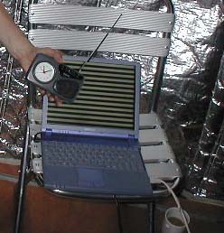
Last day to test today. We will use two 150A Lite-On LCD monitors. One for showing a full screen black and white image (text), and a AR 5000 receiver with a simple dipole antenna.
We will set the screen to 1024 x 768 @ 75Hz. First we need to work out the pixel frequency....
After a few rainy days inside we went stir crazy and made a recipe database: http://frequencyclock.montevideo.nl/opensauces/recipe.php
But now back to the research. From a friend in Dubrovnik:
http://www.radioqualia.net/makrolab/van_eck/MonitorsDB2.txt
if you havent seen this, it provides a nice summary of TEMPEST and provides many pointers to publicly available information, as well as speculation about classified documents.
http://lib.f0.am/cgi-bin/view/Libarynth/AllYouEverWantedToKnowAboutTempest
So it appears that you need a VGA multisync monitor ('multisync' means that the Vertical Deflection Frequency and Horizontal Deflection Frequency can be changed).
The VGA (Video Graphics Array) monitor has a collection of pins at the point where it is connected to the computer (or other output device), these pins correspond to the following:
* pin 1 - Red video * pin 2 - Green video * pin 3 - Blue video * pin 4 - Ground * pin 5 - Self test * pin 6 - Red ground * pin 7 - Green ground * pin 8 - Blue ground * pin 9 - No pin * pin 10 - Digital ground * pin 11 - Reserved * pin 12 - Reserved * pin 13 - Horizontal sync * pin 14 - Vertical sync * pin 15 - Reserved
If you are looking at a VGA connector with the widest point of the plug at the top and the pins pointing towards you then the pins are numbered from left to right with each row continuing sequentially from the last row.
(http://www.howstuffworks.com/monitor2.htm)
So pin 2 (Green Video) is the important pin for van Eck monitoring. This pin needs to be connected to a receiver (more about this soon) and the monitor needs to be set to the same Horizontal and Vertical Deflection Frequencies as the monitor being monitored.
The values for your monitor can be found in either the user manual, online or if you run Linux in the /etc/X11/XF86Config file.
r a d i o q u a l i a s Vaio Linux install has the following line: ModeLine "1024x768" 65 1024 1048 1208 1264 768 776 784 817
In this line the following values are: f(p) = 65mHz pixel width (x) = 1024 pixel height (y) = 768 x(t) = 1264 y(t) = 817
This means that our Horizontal Deflection Frequency (line rate) is : f(h) = f(p) / x(t) f(h) = 65 / 1264 = 0.0514
Multiply this by 1000 gives us 51.4 kHz
Our Vertical Deflection Frequency (refresh rate) is : f(v) = f(h) / y(t) f(v) = 51.4 / 817 =0.629
multiply this by 1000 gives us 62.9 Hz
It seems that we are dealing with frequencies in the 3Mhz - 3Ghz range. I believe some of the equipment here at the Makrolab is able to monitor these frequencies.
As far as I can work out there are several values that are important when doing van Eck monitoring.
They are :
Pixel Clock Frequency
Horizontal Deflection Frequency
Vertical Deflection Frequency
Pixel Clock Frequency ( f(p) ) To work this out you need to know the time it takes for the electron beam (in a Cathode Ray Tube) to travel from the center of one pixel to the center of the pixel on the right (CRT beams move from left to right). The Pixel Clock Frequency ( f(p) ) is then calculated as :
f(p) = 1/pixel time
The Pixel Clock Frequency is therefore the number of consecutive pixels that can be redrawn in one second.
The Horizontal Deflection Frequency ( f(h) ) - is the number of scanlines displayed per second if we were to exclude the time it takes for the electron beam to pass from the end of one line to the beginning of the next.Measured in kHz.
f(h) = f(p) / x(t)
Where x(t) is the time the beam takes to travel the full width of the screen (without jumping back to the beggining of the next line)
The Vertical Deflection Frequency ( f(v) ) - is the number of frames (entire screen area) displayed per second if we were to exclude the time it takes for the electron beam to pass from the end of a frame to the beginning of the next frame. Often also just called the 'refresh rate'. Measured in Hz.
f(v) = f(h) / y(t)
Where y(t) is the time required for the beam to display one complete frame.
(reference : http://pax.st.usm.edu/cmi/inform_html/glossary.html
http://www.monitorworld.com/faq_pages/glossary_page.html
http://www.monitorworld.com/faq_pages/q29_page.html)
In the 'cache' of Google: http://216.239.35.100/search?q=cache:GF7y1BtScKwC:perso.wanadoo.fr/berke/tempest/+berke+tempest+software&hl=en&ie=UTF-8
This lead to http://perso.wanadoo.fr/berke/tempest/#jmctempest. Which is the original page...
The missing page with the attack software. This is not actually what I thought it was going to be but interesting nonetheless.
Ross Anderson is the guy that has worked both with Markus Kuhn and with Microsoft (to find ways that screen emmissions can broadcast licence key numbers to help stop software pirating). Ross is at Cambridge, his web page is : http://www.cl.cam.ac.uk/users/rja14/#Tempest
In this page he has a broken link to attack software :-( . we will send him an email asking for information on how to get hold of this software.
Last year Erik Thiele (www.erikyyy.de) created an application for broadcasting sound through your monitor. He did this to how that TEMPEST, which has been surrounding by much conjecture regarding its factual foundations, can be possible.
Erik built the application for Linux ontop of an appliction originally written by Pekka Riikonen. It appears in a discussion with Rodney Berry that this method was also exploited by computer enthuisats working with Commodore 64s in the 80s (we will research this a bit more).
Erik Thiele's application works very well - by running the application on a Sony Vaio laptop we were able to play a number of tunes _through_ the emmissions made by the screen which could be picked up and played back on an AM radio. We recorded this experiment (the output from the radio) for your listening pleasure). The screen looked like differing pages of black and white static (see pic). Apparently the larger the screen the stronger the signal, ours was just a small laptop screen and the signal was recieveable only within a few inches of the laptop, however this did effectively demonstrate the principles behind van Ecks theories.
The 'Tempest for Eliza' application is supposedly able to convert normal MP3s to a format that the application can play but we have not been succesful using tjsi yet.
We experimented with Tempest for Eliza (www.erikyyy.de) and it works great! Essentially what it does is play tones through your monitor so that it broadcasts on AM...its really amazing..documentation tomorrow! Many thanks to Nik Gaffney for putting us onto this.
They also broaden the definition of 'spurious transmissions' to include acoustic emissions, such as the sounds of modems, which can be eavesdropped using a broader range of technologies including microphones. They suggest that dot matrix printers could be listened to which may mean the reconstruction of the data printed by identifying the sound made by the printer when a specific character is printed.
Additionally they suggest hackers could plant emission controlling softwares to emitt easily detectable messages, bringing hacking into the world of TEMPEST transmission techniques.
Another use for monitoring these emmissions is to monitor not the actual data emitted but to identify what process are underway when certain emissions occur. The decryption of pin cards, for example, may require a specific algorthim to be executed a certain amount of times, knowing when this algorthim is executed refines the hacking possibilities.
These two wrote a paper 'Soft Tempest: Hidden Data Transmission Using Electromagnetic Emanations' in 1998 (http://www.cl.cam.ac.uk/~mgk25/).
Ross Anderson is purportedly the person that was helping Microsoft build electromagnetic emmitting software for catching software pirating (see below).
In this document they state that both the US and german governments have known about and studied the possibilties of 'compromising emmissions' and they have developed standards by which equipment can be tested to prevent these emmissions. However both governments keep these standards and testing methods classified. NATO has similar classified documents....more soon...
Downloaded the Radio Eliza software but the SDLlib doesnt work...hmmm...will write to the author
most of today building a transmitter for makrolab - a small 1/2 Watt FM transmitter to broadcast makrolab news and music to the locals ;-)
it works good but i think we will donate it to helen for her audio installation and build a 1W transmitter tomorrow for radio free makrolab
Ok..the last bit...CRT displays work by the tube sequentially propelling electrons at each pixel on the screen. The screen is actually coated with red, green, and blue phospor and there is a dedicated electron beam for stimulating each layer. The beams are projected through a mask, this mask has tiny holes cut in it that are in fact the pixels!! When the three beams pass through a hole, they stimulate the 3 different layers of phosphor and taaadaaa! color is produced at that pixel.
http://www.howstuffworks.com/tv1.htm
LCDs work because the molecules in crystals are effected by electricity, different currents will point the molecules in different directions. It is this direction of the molecules which effects the light and determines the how much light will be passed through to the screen. The light emmitting device is usually a fluorescent tube.
The color is controlled by determing how much light should be allowed to pass through three crystal layers - one each for red, green and blue. Hence each pixel is actually made up of three sub-pixels and the color of the pixel is determined by how much light from each sub-pixel is emmitted or blocked.
ok...late start today(had issues with getting good cables for the network)...righto monitors:
There are two different major screen technologies - CRT (Cathode Ray Tube) and LCD (Liquid Crystal Display). CRTs are common for desktops and LCDs are more well known for laptops although this is changing as they become more popular for desktop displays.
Most monitors support upto 16.8 million colors at 800(horizontal)x600(vertical) or 65,536 colors at a resolution of 1600x1200 at an aspect ratio of 4:3 (although 16:9 is becoming more popular).
The data for displaying sent to the screen is sent in three seperate color signals - one for each of green, red, and blue (normal television has a composite color signal). This data is converted from a digital signal to an analog signal via a Digital to Analog Converter (DAC).
'Dot Pitch' is space between each pixel. The lower the dot pitch, the closer the pixels are together and the higher the resolution possible for the screen size.
The refresh rate of the monitor is measured in Hz - this is the number of times all the pixels are redrawn in a second. For example, a refresh rate of 72 Hz means the entire screen is redrawn 72 times every second. The higher the refresh rate the lower the amount of flicker on a screen. Television differs from LCD and CRT computer monitors by using a system called 'Interlacing'. Interlacing is the process of first redrawing all the odd lines on the screen and then going through the screen again from top to bottom redrawing all the even lines (see 'electron gun' and 'phosphors').
The color depth of a screen is the number of bits assigned to describing each pixel. A 24 bit color depth assigns 24 bits to describing each pixel, each of the additive color values (red,blue, green) get 8 bits each in this case.
CRT technology requires a larger material presence because the distance between the beam projecting device and the screen needs to be a certain length. LCD screens are thinner because they work by _blocking_ light rather than creating light (needs more research).
(see http://www.howstuffworks.com/monitor1.htm)
Almost all modern computer monitors work using raster scanning. This technology was introduced in the late 1960s for displaying monochromatic text on time-sharing computer terminals. This is the birth of the pixel as the raster scan technique required a beam to turn on and off as it scans the face of the tube leaving a series of dots (pixels) that could be interpreted as text (http://www6.tomshardware.com/business/01q3/010907/pixel-03.html).
With raster scan the updating of these pixels is done at a constant velocity. This velocity is determined by the 'Pixel Clock' (http://www.forums.pctechguide.com/glossary/wordfind.php?wordInput=Pixel). Hence the 'Pixel Clock Speed' is the refresh rate of the monitor.
It might be possible to use a simple antenna through an amplifier and a Analog to Digital Converter (eg http://www.amabilidade2002.com/toslink2.htm) and then process the data digitally....hmmm....
It is possible to actually work with these emmissions in interesting ways other than in this direct data monitoring relationship. Tempest for Eliza (http://www.erikyyy.de/tempest/) is a software that allows the control of the high frequencies emmitted from a standard monitor so that the monitor can transmit intelligable data in the AM band. The software can be used to transmit MP3s (for example) through your monitor so you can receive them on an AM radio.
It has also been suggested that controlling electromagnetic emmissions like this could be deliberately used to broadcast data from secure systems. This would mean the code could be embeded in an application to allow the transmission of certain data through electromagnetic waves, this is a similar concept to how a typical 'Trojan Horse' operates.
Microsoft has been implicated in an article ('British Technology Might Flush Out Software Pirates' By John Burgess) as a leading developer of using emmissions in this way to combat software piracy (http://lists.essential.org/1998/info-policy-notes/msg00005.html). Although this research has apparently been stopped the idea was that Microsoft could simply drive a van through a street and detect which businesses contained pirated software by monitoring the emmissions from those sites and determining if multiple uses of a single licence number was occuring.
We started research on Van Eck quite some time ago but there appears to be little on the web regarding the building of a Van Eck monitoring device. I wrote to Markus Kuhn (http://www.cl.cam.ac.uk/~mgk25/), a student at Cambridge Univesity, that has been working on Van Eck issues (especially 'optical van eck' - which is reading monitors using an optical sensor).
Mark replied with an unreleased version of his thesis (he asked us not to re-distribute this document - so we cannot post it online or email it to anyone). His thesis apparentlycovers some interesting information on how a basic Van Eck monitor _might_ be built. More when we have read it....
'Van Eck' is the name given to a process first documented by Wim van Eck in 1985 (see his original paper at http://jya.com/emr.pdf). Wim van Eck discovered that it is possible to monitor data from a computer by receiving the electromagnetic fields (EM fields) that are produced by computer and its devices. It is possible, for example, to receive the electromagnetic waves produced by a standard computer monitor, and reproduce the data being displayed on the monitor, on another screen.
This process can also be used to monitor the emissions of any computer device that is related to data traffic for the purposes of intercepting that data - modems, scsi cables, ethernet cables etc are theoretically susceptible to this kind of surveillance. Its is suggested by some that pin data entered into automatic teller devices (ATM) can be monitored in this fashion although it seems there is no documented evidence of this ever happening.
This type of surveillance is also known as 'Van Eck Phreaking' and alternatively is called 'TEMPEST' (Telecommunications Electronics Material Protected from Emanating Spurious Transmissions) by the United States of America government. Apparently the USA government started the investigation into this phenomenon in the 1960s (http://searchsecurity.techtarget.com/sDefinition/0,,sid14_gci522583,00.html) and today it is refered to by the USA gov by the term EMSEC (Emmissions Security).
Today we set up a basic network via Ipnetrouter as there was originally only 4 IP numbers possible...then we did the forum.