
| Microwave Radio Path Analysis |
| A service of GBPPR Radiation Laboratory |


Notes
EXPERIMENTAL - WORK IN PROGRESS - MAY GIVE WEIRD RESULTS
Microwave Radio Path Analysis Notes <--- Read this first!
1.) Don't forget to take into account any radome loss. For sealed Yagi antennas, radome loss is usually included in the antenna's specified gain. "Wet" radome loss can be 2 dB or more.
2.) Arvids Vigants' space diversity improvement equation is only accurate for paths with the following parameters: Distance: 14-40 miles, Frequency: 2-11 GHz, Spacing: 10-50 feet, Div. Gain: 0-6 dB of Primary, Fade Margin: 30-50 dB. The diversity antenna cable type is assumed the same as the main receiver's. Space diversity is usually required when crossing flat, wet surfaces or in very humid climates.
3.) Dispersive fade margin is provided by your radio's manufacturer, and is determined by the type of modulation, effectiveness of any equalization in the receive path, and the multipath signal's time delay. Dispersive fade margin characterizes the radio's robustness to dispersive (spectrum-distoring) fades.
4.) External interference fade margin is receiver threshold degradation due to interference from external systems.
5.) Adjacent channel interference fade margin accounts for receiver threshold degradation due to interference from adjacent channel transmitters in one's own system. This is usually a negligible parameter except in frequency diversity and N+1 multiline systems.
6.) K-Factor of 1.0 is the true Earth radius and "Infinity" is a flat Earth. Radio waves tend to "travel farther" than optical waves due to atmospheric refraction. A K-Factor less than 1.0 means the RF path bends upwards (sub-refractive) into the atmosphere, while a K-Factor greater than 1.0 mean it bends downward (super-refractive). A K-Factor of 4/3 (1.33) is often used as a compromise.
7.) Average Annual Relative Humidity
8.)
9.) The Climate Factor, or C-Factor, is a parameter in the Vigants-Barnett model used to predict outage probability. The Vigants-Barnett reliability method allows users to automatically calculate the C-Factor and terrain roughness.
10.) Example standard deviation of the terrain elevations: 29 feet - for smooth and over-water terrain, 50 feet - for average terrain with some roughness, 120 feet - for mountainous or very rough terrain.
11.) Choose a "worst case" scenario just to be safe.
12.) The first Fresnel zone corresponds to the main lobe, which contains the vast majority of the RF energy. 60% of this zone must be free of physical obstructions for the microwave path to be successful. For highest link reliability, at least 30% of the first Fresnel zone at K = 2/3 or 100% of the first Fresnel zone at K = 4/3 should also be clear.
13.) Attempts to determine you country, state, and city based on the transmitter site LAT/LON by using OpenStreetMap.
14.) Ground clutter has the effect of raising the overall terrain by the specified amount, except over areas at sea-level and at the transmitting and receiving antenna locations. The input is a generic range from 0 to 100. Select "feet" for 0 to 100 feet (1 foot increments) or select "meters" to increase the range from 0 to 330 feet (3.3 foot increments).
15.)
16.) Worldwide Map of Ground Conductivity
17.)
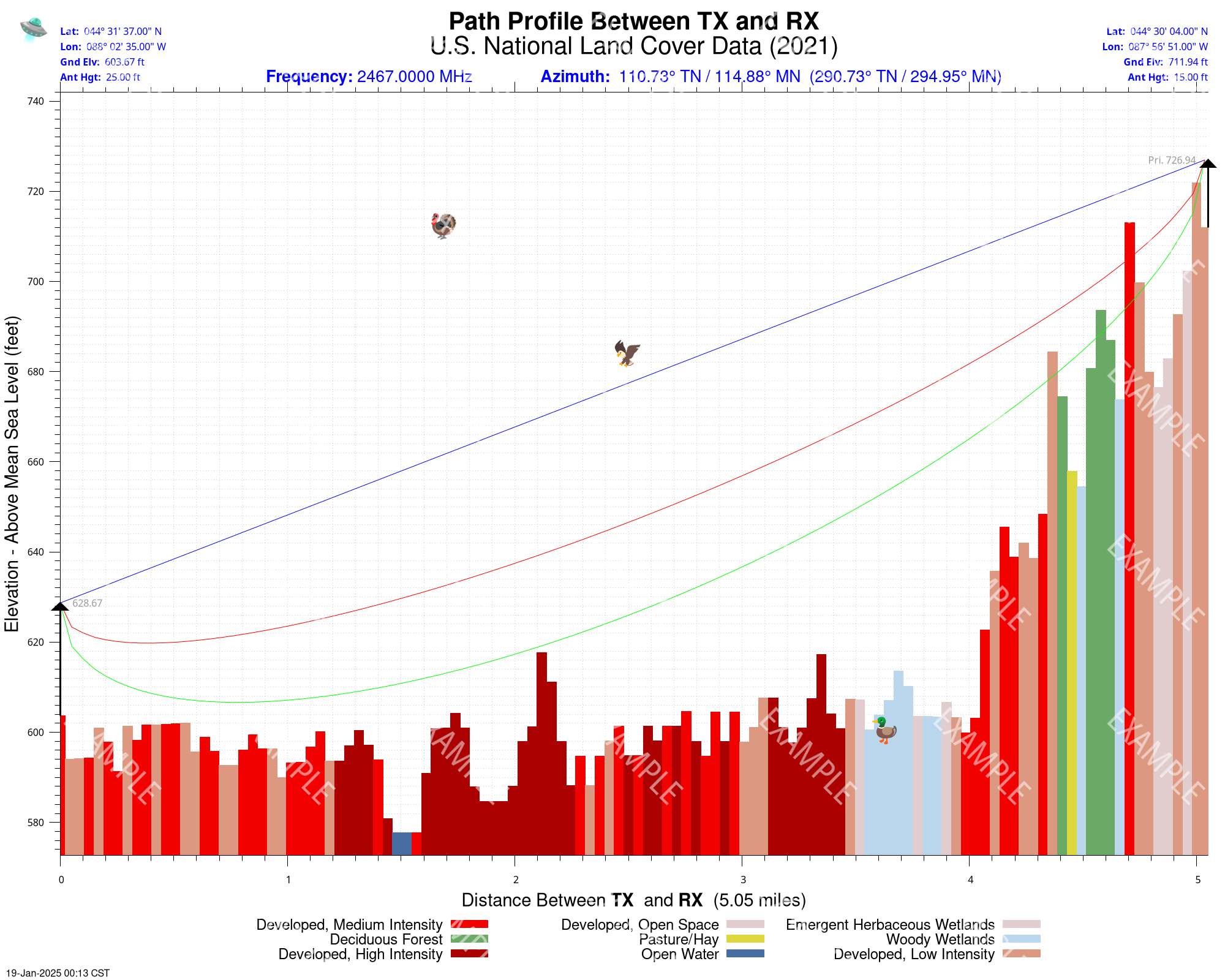
18.) Horizontal polarization will generally provide less multipath in urban areas and may provide lower path loss in non line-of-sight situations. It is also better in reducing foliage attenuation. Over water, or other flat reflective surfaces, vertical polarization will offer less path loss.
19.) Here is a good overview of Longley-Rice Situation Variability. Reception is usually described as LR(50/90). This is a 50% confidence that reception at a certain signal level will be received 90% of the time.
20.) Here is a good overview of Longley-Rice Time Variability.
21.) Low / Fast uses 3 arc-second resolution Shuttle Radar Topography Mission elevation data. High / Slow uses ASTER Global Digital Elevation (v3) terrain models. This 30-meter terrain data is higher quality, and even includes the missing SRTM latitudes. The only problem is the plotting time is quite long. Switch to High / Slow option if you get an error message stating the terrain data files are missing.
22.) Adds additional height to the plotted Earth terrain profile based on the results in the 2021 U.S. National Land Cover Database. The added heights are just educated guesses and not the actual height of the obstacles.
Plotting done using SPLAT! v2.0 by John A. Magliacane (KD2BD) and hoche.
The Elevation Profile displays the elevation and depression angles resulting from the terrain between the receiver's location and the transmitter site from the perspective of the receiver's location. A second trace is plotted between the left-side of the graph (receiver's location) and the location of the transmitting antenna on the right. This trace illustrates the elevation angle required for a line-of-sight path to exist between the receiver and transmitter locations. If the trace intersects the elevation profile at any point on the graph, then this is an indication that a line-of-sight path does not exist under the conditions given, and the obstructions can be clearly identified on the graph at the point(s) of intersection.
AGL- Above Ground Level. Height above common ground to the midpoint of the radiating antenna. AMSL - Above Mean Sea Level. Height referenced above sea level, or zero elevation.
Other Analysis Tools