GNU Radio Sample Code For Four Level FSK USRP Applications


Overview of the GNU Radio FSK 4 level example code:

Statement of design objectives:
The result is a layout where incoming data is sent through standard GNU Radio blocks that act as a channel selection filter, frequency demodulator, and symbol shaping filter before passing through a custom 4L-FSK demodulator block.

A frequency correction loop emits messages as needed to adjust the frequency offset of the channel selection filter; this is intended for coarse frequency adjustments until the 4L-FSK block can take over fine tracking.  GNU Radio messages are not suited for ultra precise feedback control because of unknown message processing latencies and inevitable delays resulting from data being processed in blocks; it is also noticeably processor intensive to dynamically adjust the frequency translating filter.  Therefore the demodulator block implements its own fine frequency tracking loop with enough range so that no frequency correction messages are emitted once a signal has been acquired.

The output of the 4L-FSK demodulator is a stream of floats at the symbol rate.  Floats were chosen for subsequent processing to allow for possible soft decision error correction as well as easy connections to a GNU Radio oscilloscope display block.

Further custom blocks display the received data stream on a console output which can be piped to a file for further analysis.

GNURADIO fsk 4 level demodulator block diagram


Operation of the four level FSK demodulator block:

The more traditional enthusiast approach to 4L-FSK involves slicing the incoming data at levels derived from tracking minimum & maximum signal levels.  This approach does indeed work well enough for certain 4L-FSK signals such as FLEX paging transmissions which we note are designed for relatively forgiving integrate and dump receivers.  This is somewhat harder to implement with channels intended for Root Raised Cosine (RRC) symbol filtering... there can be significant overshoot over the nominal symbol levels which makes it somewhat difficult to derive reliable slicing levels.  As an example, a 19.2 kbaud RDLAP signal with symbols positioned at ±1200 and ±3600 Hz may have frequency deviations as high as ±5600 Hz.

A better solution is found in the RDLAP 4L-FSK demodulator algorithm described in U.S. Patent 5,553,101).  Three quantities that characterize a received data stream are tracked: frequency offset, frequency deviation, and symbol timing.  The symbol timing clock determines when a symbol is sampled from the incoming data stream;  the frequency offset & deviation parameters are then used to make a hard symbol decision (-3, -1, +1, or +3) and to calculate an error relative to the expected symbol position.  This error is then used as feedback to update each of the three parameters using first order loop filtering and associated gain constants.

  Symbol Tracking Operations
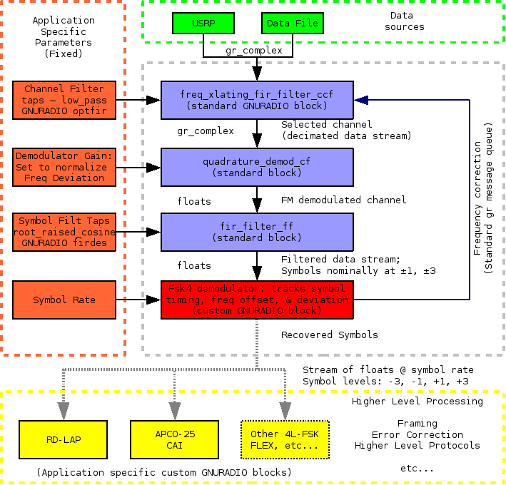
Frequency Offset
Frequency Deviation
Symbol Timing
Removes systematic offsets present on all received symbol levels.  This offset essentially is the running sum of the symbol error times a gain constant.
Tracks systematic offsets relative to center of signal.  This is a running sum similar to frequency offset but note the sign reversal for symbols (-1, -3) vis a vis (+1, +3)
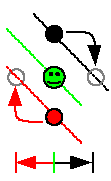
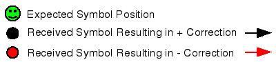
The slope of the data signal determines which direction to shift the receive clock to bring received symbols closer to the expected level.  The timing shift is proportional to symbol error with direction as indicated below.
+3

+3
Positive Slope

+1
+1
-1
-1

Negative Slope

-3
-3

All three tracking loops run once every symbol time period with no unpleasant interactions.  Lock in occurs over a broad range of gain variables.  The gains as implemented in the sample code have been chosen for rapid signal acquisition of the symbol sync sequence (~16 symbols repeating a +3, +3, -3, -3, pattern transmitted whenever the transmitter is keyed up).

The frequency offset feedback loop gain must be set high enough for rapid acquisition of the symbol sync sequence.  This requires a gain constant of around 0.1 for the fine frequency tracking loop.  As mentioned earlier there is a coarse tracking loop that may emit gnuradio messages; this tracking loop has a much slower response to prevent false triggering off of noise.

The frequency deviation and symbol timing gains are less critical.

The tracking loops themselves operate on normalized inputs.  Ignoring frequency offsets we expect symbols coming from the symbol shaping filter to sit nominally at -3.0, -1.0, +1.0, or +3.0 (stream of floats).  The frequency deviation tracking loop will adjust to signal deviation ±20% off nominal (somewhat arbitrary but seems to work well enough).  The fine tracking loop is allowed to track within a ±1.66 normalized frequency range (which corresponds to ±2kHz on an RDLAP signal that has ±1 symbols 1.2kHz out from the center of the band).  Please consider this extra frequency slop when specifying the channel filter characteristics.

Since this block operates on normalized inputs any resulting frequency feedback messages must be denormalized (turned back into Hz) before being applied as a frequency correction.  But the nice thing is that none of the constants internal to this block need to be changed when tracking data streams with different operational parameters (deviation, symbol rate, et cetera).


All gains and constants are set at the start of source file fsk4_demod_ff.h in case modifications are needed.  Operational verification can be done by graphing the demodulator output (one of the reasons it outputs in floats).


Compiling & Installing Sample Code:

Download the gr-fsk4-22Apr08.tar.gz and extract the archive package.  The package will extract into a directory called "gr-fsk4".  In that directory run the following commands:

./bootstrap
./configure
make
sudo make install (or similar)

Note: make check does not do anything; end to end qa code tests would require inclusion of transmit block for signal generation.

This generates and installs the 4L-FSK demodulator block.  The sample source code will be in the gr-fsk4/src/lib and gr-fsk4/src/python directories.

The file are based off the gr-howto-write-a-block tutorial files that come with GNU Radio; if you can get the tutorial compiled and installed then this package should work too.


Using the various 4L-FSK demodulator blocks in python:


You must import the fsk4 library from gnuradio.  You then have four blocks to work with.


Demodulator: You must pass the message queue pointer, the channel sampling rate, and the symbol sampling rate.  The message queue is used to pass frequency correction requests to frequency translating filter.

Example:        self.demod_fsk4 = fsk4.demod_ff(queue, self.channel_rate , self.symbol_rate)

If you wish to have streaming data going to the console you should also use one of these blocks:


RDLAP Protocol Processing:  Pass the message queue and a processing flag.  At this time no messages are created by the RDLAP block (future expansion).  Only the lowest order bit of the processing flag is is used; when set the incoming data stream will be inverted.  Inversion should not be necessary when using the USRP.

Example:        self.protocol_processing = fsk4.rdlap_f(queue, processing_flags)

This block frames the incoming data, splits out data blocks, de-interleaves, performs error correction, and displays each block on the console as a sequence of 12 data bytes per line.  An extra line is inserted at the end of each PDU for easier visual inspection.  It is suggested to pipe this output to a file for further processing.  All header blocks have passed a CRC check; bad header blocks are not shown.

No higher level processing takes place on each block.  Remember, if you often see something like a "78 9C" near the start of multi line data blocks then you seriously need to look at sending this data through one of the free deflate algorithm implementations such as zlib.


APCO-25 Protocol Processing:  This is a stub block that detects the frame sync and displays the network address code and the data unit ID on the console.  No error correction is implemented & no further processing is done.  The message queue is currently unused; bit zero of the processing_flags can be used to enable frequency inversion.

Example:        self.protocol_processing = fsk4.apco25_f(queue, processing_flags)

Further development is not expected due to a current lack of exploitable APCO-25 signals.


Generic Block: Pass the message queue and a processing flag. The lowest order bit of the processing flag can be used to invert the data stream if needed (matches RDLAP block behavior).  The message queue is currently unused; bit zero of the processing_flags can be used to enable frequency inversion.

Example:        self.protocol_processing = fsk4.generic_f(queue, processing_flags)

This takes the demodulated FSK4 data stream and send the raw symbols out to the console.  It was decided that it would take up too much space to print "-3", "-1", et cetera so instead the following convention was chosen:  Each symbol is printed as a single character starting with 'A' for -3 and going all the way through to 'D' for +3.  It is assumed that the output is piped to a data file for further analysis of unknown protocol formats.


Configuring the python code for signals of interest:

Vital Statistics of Two Implemented Examples
Signal Type
RDLAP 19.2 kBaud
APCO-25 C4FM
Bit Rate
19.2 kBaud
9.6 kBaud
Channel Spacing
25kHz
12.5kHz
Deviation (Hz)
Defined as frequency offset to ±1 symbols
from center of band

1200 Hz
600 Hz
Symbol Rate
9600 ksps
4800 ksps
Receive Symbol Shaping Filter
RRC
(alpha = 0.2)
RRC
(alpha = 0.2)

The example code usrp_fsk4.py and usrp_fsk4_oscope.py implement the above two protocols.  Everything is grouped together in one common location allowing easy customization and testing of virtually every parameter.  As an example we show the APCO-25 C4FM example block:


          self.symbol_rate = 4800                        # symbol rate; at 2 bits/symbol this corresponds to 19.2kbps
          self.channel_decimation = 20                # decimation
          self.max_frequency_offset = 6000.0    # coarse carrier tracker leash
          self.symbol_deviation = 600.0               # this is frequency offset from center of channel to +1 / -1 symbols
          self.input_sample_rate = 64e6 / options.decim        # for USRP: 64MHz / FPGA decimation rate   
          self.protocol_processing = fsk4.apco25_f(self.msgq, 0)
          self.channel_rate = self.input_sample_rate / self.channel_decimation

          # channel selection filter
          channel_taps = optfir.low_pass(1.0,   # Filter gain
                               self.input_sample_rate, # Sample rate
                               5000, # One-sided modulation bandwidth
                               6500, # One-sided channel bandwidth
                               0.1,   # Passband ripple
                               60)    # Stopband attenuation

          # symbol shaping filter
          symbol_coeffs = gr.firdes.root_raised_cosine (1.0,   # gain
                                          self.channel_rate ,                       # sampling rate
                                          self.symbol_rate,                         # symbol rate
                                          0.2,                                               # width of trans. band
                                          500)                                              # filter type


We see where the symbol rate and frequency deviation are set.

The channel decimation is set to 20.  This means that with a USRP sample rate of 64MHz, a user decimation option of 256, and this channel decimation of 20 we end up feeding samples to the demodulator block at 12.5 kHz.  This rate should at a minimum be several times the symbol rate which is a criterion we satisfy.  The coarse tracker is limited to about ±½ the channel bandwidth (really a rather arbitrary choice).

Higher level protocol processing is to be handled by the apco25_f block.

And some more filter setup and we are good to go...


Sample Application Description:

The gr-fsk4/src/python directory contains the usrp_fsk4.py and usrp_fsk4_oscope.py examples.

The usrp_fsk4.py is intended to run off both the USRP and saved data files (assumed 32 bit floats).  It is based off the usrp_flex.py example so we basically have the same options with the following changes:  Log files (option "-l") generate an additional output file called "demod.dat" which is the symbol stream output.  This is in addition to the channel file ("chan.dat") and ("usrp.dat") if data is being taken directly from the USRP.  We recommend the baudline signal processing package to analyze these data files.  An additional option "-p" is available to select the desired protocol.


Example:    ./usrp_fsk4.py -F filename.dat >demod_text.txt


Next, we made an example where we planted the 4L-FSK application code in the middle of the usrp_oscope.py utility.  Not all usrp_oscope.py parameters will work in this application.  "-8" causes problems for examples.  The decimation control was disabled because there was no super easy way to change decimations on the 4L-FSK processing on the fly.

The resulting usrp_fsk4_oscope.py produces the following screen output when correctly processing a 4L-FSK signal.

FSK4 Oscope Example Application


Live graphs are neat.  Here we have the incoming data signal on top and the demodulator block output on the bottom.  4L-FSK demodulator performance can be assessed immediately - you should see a set of nicely separated data symbols as in the example above (after setting the graph format to "plus" style).  This real time display is quite handy for optimizing the system.

Console output showing the demodulated data can be directed to a file as needed.


It is suggested to stick with decimations of 256 although others can be specified if desired.  The decimation setting is applied to both the USRP and input files (on input files it is assumed that the decimation setting was that of the USRP taking the data).


Closing Comments:

There are no updates anticipated for the APCO-25 processing code.  This is primarily due to a lack of accessible and exploitable APCO-25 signals.  While this 4L-FSK demodulator block appears to work well on C4FM APCO-25 samples one should think towards the future and work and implement a combined C4FM / CQPSK demodulator.  Such a demodulator block will not work for RDLAP applications though.

No attempt has been made to receive any other 4L-FSK signals such as FLEX paging.  This is probably best handled with the GNU Radio FLEX blocks which implement a fully functional FLEX receiver with several example applications.  It is suspected that the methods described on this web page would be needlessly complex for FLEX signaling.


Copyright Disclaimer: 

The code described on this page borrows heavily from various GNU Radio examples and components which fall under the GNU General Public License.  All additional modifications and code added for this project also fall under GNU General Public License.