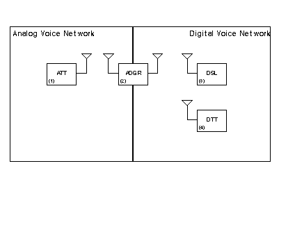
 The functions of the ADGR are:
In order to increase the synergy and number of users involved in the project, it is also proposed that the system be linked to Vancouver, via the Telesat wormhole, as well as providing an Analog to Digital gateway for Ottawa based uses.
The system is based on using DSPs to digitally encode the voice signals at rates less than 16 kbps. One of the purposes of the testbed will be to evaluate various voice encoding techniques that are publicly available, and to evaluate DSP capabilities. The long term goal of this experiment it to facilitate and provide some practical experience in the future recommendation of a digital voice encoding standard for Amateur Radio.
The figure below shows the functional block diagram of the ADGR.
The functions of the ADGR are:
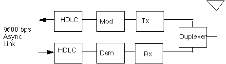
1) Dup: Duplexer, allow the simultaneous reception and transmission of voice signals.
2) Rx: Receive narrow band FM voice signals and output baseband audio.
3) A/D: Analog to digital conversion of the baseband voice signals.
4) Encode: Digitally encode and compress the digital voice signals,
5) UDP/IP: Packetize the digital voice stream into a standard packetized voice packet. This will not be a full blown TCP/IP protocol stack, it will be a minimum implementation, possibly with only one transmit (or To: field) address (perhaps the broadcast address).
6) HDLC: Encapsulate the packet into a frame for transmission.
7) Mod: Modulated the digital signals for transmission,
8) Tx: Transmit the modulated signal on an RF carrier,
9) Rx: Receive modulated digital signals,
10) Dem: Demodulate the digital signals,
11) HDLC: Decode the HDLC frames, determine the beginning and end of frame. If a CRC error is detected frame will either be discarded, or optionally sent on for possible decoding,
12) Decode: Decode the digitally encoded voice signal and output a PCM digital stream,
13) D/A: Digital to Analog conversion, take the digital stream and regenerate the analog voice signal,
14) Tx: Transmit the voice signal with FM on a conventional NBFM carrier.
15) DTMF Decode: As an option a DTMF decoder will be provided to allow the ATT users to generate signaling on the digital side. The signaling could be addressing information, or simply to activate the digital transmission.
16) ADGR Controller: This controller is the housekeeping controller of the ADGR. It provides monitoring and control functions of the digital functions.
Physical Architecture
There is a rather natural break in the distribution of the functional blocks described above and physical units. The diagram below shows the functional blocks which can be provided by physical subsystems.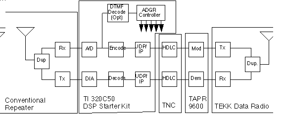
The TI starter kit should be an adequate platform for testing the system with. It is also a low cost completely self contained platform that offers all the tools and hardware required to build the subsystem. The Kit comes complete with A/D, D/A, a DSP engine, software tools and debuggers, and a computer interface.
The TNC is a conventional TNC with modem disconnect header or with 9600 baud modem installed.
The 9600 baud modem could be either the TAPR modem kit or a prebuilt modem.
The Data Radio is proposed to be the TEKK radio, as a low cost self contained package. However, a conventional repeater would also be suitable if the IF strips are wide enough.
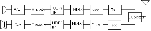
The physical architecture of the DTT could be the same as the ADGR or it could be as shown below.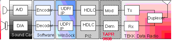
DSP Starter Kit $99.00
TAPR Modem: $75.00
TNC: Scroungable
Data Radio (TEKK): $99.00
Total: 273.00
Tax + Exchange: $360 CND
Misc. other parts: ??
The challenge is to implement a DSP vocoder that will run in real time on an inexpensive DSP platform. It has been done before by commercial interests, so we know it can be done - all we have to do is: just do it!