X-Box Behaviours
I2C x-Box code from Jarin the PenguinJarin the Penguin posted the following code to XBOXHACKER, which is interesting as it exposes the I2C controller footprint in the X-Box IO space and shows how to use it. (You should note this code has a subtle bug, smalldelay() will be return immediately occasionally when it is called just as GetTickCount() is going to be updated after the first line. Also, at least on a PC, the resolution of GetTickCount() is 20 or 50 mS units at a time typically, the scheduler timeslice size). Just in case I wasn't clear enough, this is not my code, it is in the public domain now and we can thank Jarin the Penguin for sharing it.
I2C traffic analysis
|
| 54h |
EEPROM |
| 10h |
PIC |
| 45h |
Conextant Video encoder |
| 4Ch |
ADM1032 System temperature monitor |
It is suspected some interesting watchdog type traffic is issued during the startup sequence, which should now be available in these dumps for people to try. Remember, these addresses need doubling to conform to x-Box terminology. (thanks again to visor for describing 45h and 4Ch devices)
Note on safety
Your X-Box floats - it doesn't have an earth connection. There
is quite a difference in potential between a standard X-Box and earth ground;
I can make little sparks by touching the chassis of the X-box with my eath-ground
scope probe ground clip. You will likely damage your PC if you attempt
to connect it without ensuring that the X-Box agrees with your PC about the
relative potentials of 0V and Earth Ground.For a while I clipped a couple of scope probe ground clips to the chassis and made do. But today I was indirectly connecting my beloved laptop to the X-Box, so I took a precaution I strongly recommend to anyone doing the same.
I cut off the mains plug from the X-Box power lead and substituted my own non-moulded one, then added a thick wire from the earth pin of the mains plug, neatly tie-wrapped to the mains cable, and bolted the other bared end on to the chassis of the X-Box. (If you are not sure which pins are which in a mains plug, please do not experiment, go get someone else who does know to do it for you). Take care to bolt the wire in such a way that it cannot fall into the switchmode powersupply, ie, on the outside of the chassis, not the inside.
PIC examination
The PIC is a 28-pin SOIC marked PIC16LC63A. I got ahold of
the datasheet from Microchip Technology.Before we get on to the I2C traffic, I examined what happened if I connected each non-powerail pin to ground and 3.3V.
| pin |
name |
when set to |
action |
| 1, 12, 16, 18 |
nMCLR, |
0V |
X-box powers down |
| 13 |
0V |
Processor fan runs for duration |
|
| 21 |
RB0/INT |
0V |
Crashes X-Box, with dynamic video noise overlaid
on last video image (presumably by overflowing the stack with interrupt requests) |
| 22 |
3.3V |
blanks video for duration |
|
| 23, 24 |
0V |
Video blanks for one second, and then shows
X-Box logo. Note that if these pins are grounded while the intro movie
is playing, the movie is aborted, and after one second we go straight to
the X-Box logo display |
|
| 14/15 (I2C) |
SCL, SDA |
0V |
See below |
The PIC takes the I2C bus signal SCL and SDA in on its bottom two pins, p14 and p15.
I got out my old HP1650A logic analyser and hooked it up. It was hard work as it is too old (1987!) to reassemble the serial data and had to be decoded by hand. I ran up the X-Box two times. Note that the I2C protocol allows an arbitrary number of data bytes to follow an address.
<bogus values removed 2002-06-13 to avoid confusion>
I couldn't make much sense of it, I would suggest that my interpretation of the data is at fault, but there was very good correspondance with the ACK/NACK bits. These were captured from startup, perhaps there was crap or multiple startups as the power came up. If I have time later I will look at them again.
Despite a not very satisfactory attempt to snoop the I2C, Just by monitoring SDA and SCL with a 'scope while the X-Box sits on its language selection display I can see that there is no activity on the I2C bus at all while it is sitting there waiting for someone to press something. So the idea that there is a watchdog in the PIC that needs stroking over I2C is demonstrably wrong.
Here is a look at the PIC while sitting on that display: (low means static 0V level, high means static 3.3V)
| 1 |
high |
| 2 |
high |
| 3 |
low |
| 4 |
high |
| 5 |
high |
| 6 |
high |
| 7 |
high |
| 8 |
low |
| 9 (clk in) |
clock - 10MHz 3.3V |
| 10 |
10MHz sawtooth from crystal tank circuit |
| 11 |
low |
| 12 |
high |
| 13 |
high |
| 14 |
high |
| 15 |
high |
| 16 |
high |
| 17 |
low |
| 18 |
high |
| 19 |
0V |
| 20 |
3.3V |
| 21 |
high |
| 22 |
low |
| 23 |
high |
| 24 |
high |
| 25 |
high |
| 26 |
low |
| 27 |
low |
| 28 |
low |
Its clear from this that if the bios code watchdog is active while sitting on the language select screen, then the bios code watchdog does NOT live in the PIC, not a single pin was changing state.
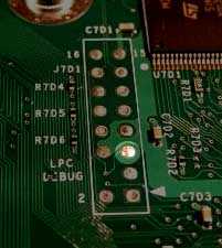
LPC investigations
This is the 16-pin connector that is not fitted to a retail X-Box, but has the space for it reserved on the motherboard. These are very friendly pads, standard 0.1" pitch pins which most people would be able to solder without problems.LPC is a 33MHz 4-bit parallel bus protocol designed (by Intel) to replace the old ISA bus, with its huge clunky connector, by a bus with far fewer pins (as little as 12). It has similar performance to the ISA bus, so while its useful for many things it won't be replacing PCI or AGP.
It was suggested to me that if you boot the X-Box while holding flash pin D0 to ground, that the X-Box would attempt to execute code from a ROM on the LPC header. I found this hard to credit, but to my surprise it seems to be true; at least, I monitored interesting things happening in that circumstance.
When you power up an X-Box normally, I observed that it issues an LPC IO Write of the value 55h to IO address 2Fh. I believe this is something to do with PnP type initialization, in case there are any such devices on the LPC bus.
When you hold pin D0 on the flash bus low during power up, you instead get an LPC read of memory address FF00007x (the x is where I ran out of space on my scope display). This is quite encouraging. I was looking this hard in order to determine that the X-Box was not using LPC DMA to get the memory, which would have been considerably more complex.
How the X-box controls the flash enable signals
The X-Box does not attempt to drive nCE, nOE and nWE; instead it pulls them to 0V, 0V and 5V respectively via individual 10K resistors. So it is simple for Milksop to connect to these signals and drive them to the desired levels.
Note also that as shipped, the X-Box CPU cannot perform write or erase actions to the flash; there is a small jumper on the reverse of the motherboard which is shipped open, disabling the write capability.
X-box behaviour without IDE drives
With the X-Box hard-drive and DVD-Rom drive unplugged, using the original flash BIOS, the X-Box powers up to display its introductory animation, and then sits there. After 23 seconds, it times out and displays a ''Your X-Box needs servicing'' message on the display device.
The flash device experiences a burst of read accesses shortly after
power-up, and is left in a fixed state during the opening animation
and subsequently until the power is removed., which is at address
offset 0xF805F. This is not useful for our purposes, as we would
find it impossible to defeat all those n-channel transistors driving the
signals low without serious heating of the X-Box driver chip and perhaps
disturbance of its local 0V level.
Forcing the X-Box into a 'warm reset'
|
|
However, applying 0V to pin 5 of the LPC connector (LRST#,
or system reset signal) has a dramatic effect. If you do this during
the opening animation, it freezes where it got to and sits there. If
you do it in the ''servicing'' display, the screen is filled with a light
grey rectangle and the X-Box continues to sit there. But either
way, the result of this partial reset is that now the Flash Address bus
is set to 0xFFFFF, that is, all of the Flash address lines are set to
3.3V. My X-Box has been in this state for several hours without
any signs of distress, I believe it is not at all dangerous to its health. |
Experiment confirming we are able to override signal driven high
by X-Box using XC95108 IO
I confirmed we will be able to successfully override the address
lines with our design by hooking a low-drven output from a existing XC95108
design I have here on to the high-driven flash address pin. It reduced
the level on the pin to 0.8V. On the face of it this is barely adequate,
because the flash device in my x-box (an ST M29F080A) features TTL-level
inputs, which specify Vin <= 0.8V as a low, and >= 2.0V as
a high.
Experiment confirming overriding address line to 0.8V is adequate
However, the following experiment leads me to believe this is not
a problem in practice. I warm reset the system as described above,
and monitored the flash D6 signal and the flash A2 signal on a dual-channel
'scope. As described, A2 is being driven to 3.3V by the X-Box as
are the rest of the address lines. D6 is being driven high by the
flash because the byte at address FFFFFF in the flash has b6 set. I
chose D6 and A2 because I noted that by forcing A2 to 0V, and so selecting
flash address FFFFB, this caused the flash to drive D6 low, because the
byte in the flash at address FFFFB has b6 clear. In this way I can
see if the flash believes I am giving it a high or low level on A2.
| Resistor from A2
to 0V |
A2 voltage |
D6 |
So flash understood
A2 as... |
| none |
3.31V |
5V |
high |
| 100R |
2.43V |
5V |
high |
| 47R |
1.83V |
5V |
high |
| 30R |
1.49V |
0V |
low |
Its clear then that in fact on the chip I looked at, the transition
between 0 and 1 takes place between 1.49V and 1.83V, leading me to believe
that driving to 0.8V is in fact perfectly adequate, in fact it gives >
0.7V margin on the chip I looked at.
Estimation of X-Box P-channel Rdson
Considering the 100R case above, the p-channel X-Box driver is dropping
0.88V with a load of 100R to 0V, while there is 2.43V across the resistor.
This shows that the X-Box driver P-channel Rdson is ~35R.
Estimation of excess current caused by forcing X-Box address line
low via XC95108
We saw that the XC95108 IO driving low was able to bring the X-Box-driven
address line from 3.31V to 0.8V. Now we know the driver has an Rdson
of 35R, this shows that the XC95108 N-channel Rdson is ~11R.
Also, this same scenario shows that the X-Box driver is dropping
2.5V across 35R, which shows ~70mA of current per overridden pin is being
dissipated in the X-Box driver chip, or 175mW.
So considering the worst case, when we are overriding all 20 address
lines, necessary for accessing address 00000, we will be causing 20 x
70mA = 1.4A to dissipate in the X-Box driver chip, or 3.5W..
Note on 2002-06-11: I have changed to using 74LVXC4245 buffers to drive, which have a 5.5R Vdson, and I have followed them with a 10R series resistor. So the aggregated Rdson will be approximately 15.5R, instead of 11R, reducing the current somewhat.
Duty cycle averaging
Although the numbers sound frighteningly large, they ignore the fact that our CPLD is smart enough only to drive the busses for the minimum time needed to perform the flash bus cycle. For a program operation this consists of a 150nS period of forcing the X-Box address bus followed by 8uS typ waiting for the flash to complete the program operation. So on average, even if we were sat there repeatedly programming the worst case address 00000, to find the average current we can divide the peak current by a factor of 8uS/150nS = 53, or a more manageable 26mA / 66mW. And in practice on average half of the bits will be high and so not being driven low.Its a similar story for the read operation, the CPLD issues a single flash bus cycle of 150nS and then time is spent transferring the data back to the PC in two nybbles. This will easily take longer than the 8uS per byte programming time.
Because the timing and control of the Milksop bus cycles are issued by dedicated hardware in the CPLD independent of the PC, we need not consider problems like OS scheduler taskswapping, where our application goes dead for 50mS at a time, perhaps at an inconvenient moment, yet another reason not to rely too much on a PC application.
So because of the low duty cycle of the high-current operations, the average current is reasonably low. The main point to watch is that the decoupling capacitors on the Milksop are capable to provide these high momentary currents without causing the main power supply rail to droop.
(NB In fact until I performed these experiments tonight, the VHDL for the CPLD would sit in a loop reading from the flash after a program or erase operation waiting for the flash to complete. I will be changing this to use the status toggle technique that will allow flash reads from FFFFF to be used, involving no high-current actions and so being able to exploit the low duty-cycle).
X-Box specific considerations
Two important notes on X-box compatability:
- The X-box ground 'floats', as there is no connection through to the mains Earth pin. As we will be connecting it to the PC, which does have a true Earthed ground, it is important that this is done while the X-box is powered down and not disconnected until the X-box is once again powered down.
- The X-box appears to drive the flash nRP pin with a normal digital level. This pin can be used to temporarily unprotect the flash blocks, by bringing the pin to 12V. Obviously that will not be possible while the flash is soldered in the X-Box. For this reason, assuming MS wanted to leave the door open to upgrading their flash, I assume that the flash blocks are not protected, and so Milksop does not have the capacity to drive nRP to 12V.
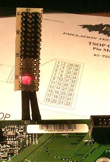
TSOP Header hack
As the TSOP header is on a four-week lead time, I decided to hack an electrical equivalent together on an X-Box (according to Bunnie's pinout diagram) so the whole project would not be delayed: