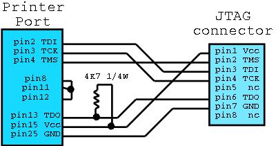
ScopeCheaptag is the equivalent of a Xilinx Parallel Jtag programming cable which you can make up from bits and pieces of dead ISA cards and old wires that are lying around. It is intended to cost nothing at all, even if you bought all the parts it would be a couple of dollars. OverviewXilinx FPGAs and CPLDs use a serial protocol called JTAG to get
programmed. Xilinx offer the software for free on their website, see
their Webpack download. Together with this minimal cable, you will then be able to reprogram
Xilinx CPLDs, allowing you to build and modify the other projects on this
site. Principles
Implementation
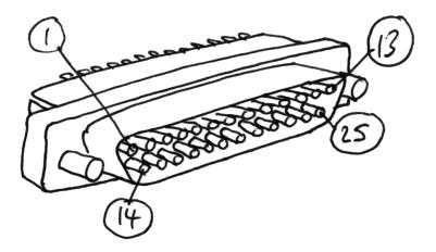
You need a 25-pin male D-connector, preferably with solder bucket termination (these are little cups that make it easy to solder wires to the connector). I only had a rightangle one lying around the office, of course that worked fine. You can find these lying around on scrap ISA printer port expansion cards. Here is a little reminder of which pins are which on a 25-pin male D-connector: 
The other end is an 8-pin SIL socket, I cut down a 10-pin shell I had lying around and used proper crimp pins. If you are trying for the coveted zero dollar method, you can use part of a ribbon cable connector and use the ribbon cable as the wire. Anything will work, so long as the wires are < 30cm or so. If you have a dead PC case lying around (you knew there was a good reason you kept it, didn't you?) you will find suitable connectors and wires in there which hook the front panel switches and lights to the motherboard. If you don't have a 4K7 (ie, 4.7K or 4700 ohm) resistor lying around, look on any scrap PCBs you have for one, its a common value. Anything from 3K3 - 5K6 will do. The usual colours for 4K7 are Yellow- Violet - Red (and gold or silver). Check it with an ohm meter to make sure you are using what you think you are. If all you have is a surface mount resistor, that's fine, it should be marked 472. 
A note on soldering wires, the number one newbie mistake is to have
strands of not-very-well-soldered wires reaching out when the wire gets twisted
and shorting to things they shouldn't. So a wise old hand strips only
the short length of wire that he needs, 3- 5mm, twists the exposed wire a
little so it forms a single unit, and tins it with a little solder. When
this wise ancient comes to solder the wire to something, they also tin the
destination pin with some solder first, too. Then they hold the two
together in a good way, and heat them with the soldering iron, usually no
additional solder needed at that point. As both the wire and the pin
are nicely covered in solder already, it melts and merges the two in a good
strong way, without excess solder or poor joints. The black objects covering the soldering on the photo above are
small lengths of heatshrink tubing. Giving a professional and safe
finish (if such words can be applied to the blatant hackjob these 'cheap*'
projects are) heatshrink tubing also takes some of the strain of moving wires
away from the solder joint and generally improves reliability. Testing
|
||||||||||