ScopeFiltror is a small device designed to:
The need the device fulfils is to facilitate rapid debug and communication with an LPC-enabled host and a PC. The design schematics, gerbers and C & VHDL sources are being released under the GPL, others are encouraged to duplicate our design when it is proven. However, as with all GPL projects, no warrenty at all is given about the performance of this design. It might do anything up to and including destroying the planet you are on if you build one. However I believe it will eventually perform as suggested. Overview
Principles
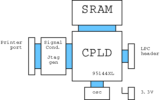
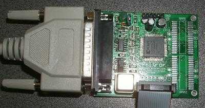
ImplementationPhyscial hardware
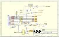
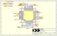
Milksop uses a Xilinx XC95144XL CPLD in a TQ100 package. Schematics
|
|||||||||||||||||||||||||||||||||||||||||||||||||||||||||||||||||||||||||||||||||||||||||||||||||||||||||||||||||||||||||||||||||||||||||||||||||||||||||||||||||||||||


| Qty | Type | Component ID | Description | part code |
| 7 |
100n | C102 C110 C111
C112 C113 C3 C4 |
1206 capacitors | Farnell 644-316 |
| 1 | 330pF | C2 | Farnell 757-251 | |
| 1 | 100uF 6V3 | C105 | submin electrolytic | Farnell 334-9913 |
| 1 |
10uF 6V3 |
C104 |
Farnell 490-659 |
|
| 3 | 100R | RP1 RP2 RP3 | 1206 quad respack | Farnell 196-710 |
| 1 | 1K | RP4 | Farnell 196-770 | |
| 1 | 4K7 | RP5 | Farnell 196-812 | |
| 1 |
33K |
R101 |
1206 single resistor |
Farnell 613-885 |
| 1 |
470R |
R102 |
Farnell 613-666 |
|
| 2 |
4K7 |
R1 R2 |
Farnell 613-782 |
|
| 1 | 74HC14 | U1 | SO-14 hex schmitt trigger | Farnell 379-268 |
| 1 |
74HC157 |
U2 |
SO-16 Quad 2:1 mux |
Farnell 379-402 |
| 1 | XC95144XL-10TQ100C | CPLD | Xilinx CPLD | Xilinx Website |
| 2 | BAT42 | D1 D2 | schottky diode | Farnell 367-783 |
| 1 | OSC20MHz | OSC1 | 8-pin DIL can
Oscillator Module (nb specified for 5V Vcc but tested to work on 3.3V Vcc) |
Farnell 788-491 |
| 1 |
AS7C34096-12JC |
RAM1 RAM2 |
4Mbit SRAM |
Farnell 385-1114 |
| 2 |
2SK1336 |
Q1 Q2 |
N-channel Mosfet |
Farnell 353-024 |
| 1 | DB25M | PRINTER | Right-angle 25-way D connector male | Farnell 892-440 |
| 1 | HEADER 8X2 | LPC | DIL 0.1" pitch header posts, 2x8 way | Farnell 511-821 |
| 1 |
HEADER 6 |
HOST |
SIL 0.1" pitch header posts |
Farnell 511-742 |
| 1 |
HEADER 2 |
CFG |
SIL 0.1" pitch header posts |
Farnell 511-705 |
| 2 |
Ribbon sockets |
IDC Ribbon Cable skt 16-way |
Farnell 316-6879 |
|
| 1 |
For host cable |
Crimp housing |
Farnell 183-3248 |
|
| 1 |
Crimp terminal strip |
Farnell 182-3218 |
||
| 1 | LED | LED1 | Green power LED | Farnell 621-006 |
CPLD Logic
Second draft of VHDL 2002-06-27
SVF file ready to program with milk
Host Cable
The host connector has the following pinout:
1: GND
2: (key)
3: nportNoLpcYet (for X-Box, hook to flash bus D0)
4: 3.3V 'always on' power supply input
5: see below
6: see below
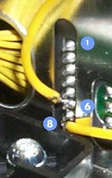
Pins 5 & 6 hook to active-low reset signal; for X-Box they need
to be wired to the front panel connector pins 6 and 8 as shown below (the
pin numbers refer to the connector shown, not the Host connector on Filtror)
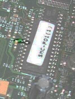
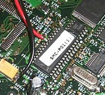
Pin 4 of the host connector needs to be connected to an always-on
3.3V supply rail. For the X-Box, this can be taken from p21 of the PIC,
or for easier soldering, the end of the capacitor that this pin is also connected
to. 0V is easily available from a nearby capacitor.
Debug connector
The Debug connector just brings out some unused IO from the CPLD
to a place where I can monitor them easily. I will be using this IO
to help me see what is going on inside the CPLD if things are not working
properly. It also allows some extra signals to be added on to the design
if someone has a bright idea.
CFG connector
This two-pin header is left open for normal operation. To set
Filtror into Xilinx configuration mode, where it looks like a Xilinx Parallel
cable is already connected to the CPLD, link the two pins. After configuration
(or reconfiguration), remove the link for normal operation.
Progress 2002-07-03
|
Completed Write and compile logic for CPLD |
||||
In
Progress
|
||||
|
Todo
|
¹X-Box is a registered trademark of Microsoft Corporation, nothing to do with us.