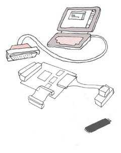
ScopeMilksop is a small (2.25" x 3") device designed to:
The intention is to facilitate rapid and repeatable changes to the content of the flash to allow new code to be tried easily. It is hoped it will be of some use to people looking to boot linux on an X-Box. The design schematics, gerbers and C & VHDL sources are being released under the GPL, others are encouraged to duplicate our design when it is proven. However, as with all GPL projects, no warrenty at all is given about the performance of this design.
Overview
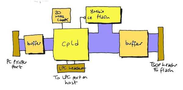
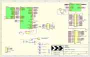
As you can see Milksop has three main interfaces:
There are in turn three main modes it is expected to find a use:
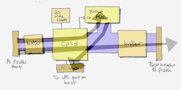
1) The printer port can be used to program the flash on the Milksop
(top arrow) (working 2002-06-16) In addition there are some handy features like automatic X-Box power
cycling after updating the flash, useful for software developers. PrinciplesIn-system flash programmingFor generic devices using TSOP flash, it is usually possible to get the rest of the devices on the bus to float their IO, either during reset or by applying appropriate levels to test pins or output enables. Milksop is generally useful in cases where there is no provision to allow flashing via the normal bus master (ie, you can't get the device CPU to do the flashing for you). Milksop is powered entirely from the TSOP device being programmed,
not only is Milksop intended to be used without removing the
device, but it is intended that the device is powered. Important note: Milksop must not be removed from the
device it is programming while power is applied. Flash device endurance
|
|||||||||||||||||||||||||||||||||||||||||||||||||||||||||||||||||||||||||||||||||||||||||||||||||||||||||||||||||||||||||||||||||||||||||||||||||||||||||||||||||||||||||||
| Qty | Type | Component ID | Description | part code |
| 13 |
100n | C101 C102 C103
C202 C203 C3 C4 C401 C402 C403 C404 C405 C406 |
1206 capacitors | Farnell 644-316 |
| 1 | 330pF | C2 | Farnell 757-251 | |
| 3 | 100uF 6V3 | C201 C105 C106 | submin electrolytic | Farnell 334-9913 |
| 1 |
10uF 6V3 |
C104 |
Farnell 490-659 |
|
| 5 | 100R | RP1 RP2 RP3 RP407 RP408 | 1206 quad respack | Farnell 196-710 |
| 1 | 1K | RP4 | Farnell 196-770 | |
| 1 | 4K7 | RP5 | Farnell 196-812 | |
| 6 |
0R - NB ECN1 |
RP401 RP402 RP403 RP404 RP405 RP406 |
Farnell 776-579 |
|
| 1 |
33K |
R101 |
1206 single resistor |
Farnell 613-885 |
| 1 |
470R |
R102 |
1206 single resistor |
Farnell 613-666 |
| 4 |
47K |
RA401..RA404 |
1206 10-pin octal bussed resistor net |
Farnell 335-2328 |
| 1 |
820R - NB ECN1 |
RX1 |
1/4W 820R single resistor |
Farnell 509-152 |
| 2 | 74HC14 | U1 U2 | SO-14 hex schmitt trigger | Farnell 379-268 |
| 3 |
74LVXC4245 |
U401 U402 U403 |
Octal level converter
/ buffer |
Farnell 642-526 |
| 1 | XC95108PQ100C | U201 | Xilinx CPLD | RS 235-8389 |
| 1 | BAT42 | D1 | schottky diode | Farnell 367-783 |
| 1 | OSC20MHz | OSC1 | 8-pin DIL can Oscillator Module | Farnell 788-491 |
| 1 |
M29F080A90N1 |
U102 |
8Mbit flash |
Farnell 333-5150 |
| 2 |
2SK1336 |
Q1 Q2 |
N-channel Mosfet |
Farnell 353-024 |
| 1 |
LE30ABZ |
U104 |
3.3V regulator |
Farnell 352-9990 |
| 1 | DB25M | J1 | Right-angle 25-way D connector male | Farnell 892-440 |
| 1 | HEADER8 | J3 | SIL 0.1" pitch header posts, 8 way | Farnell 671-964 |
| 1 | LED | LED1 | Green power LED | Farnell 621-006 |
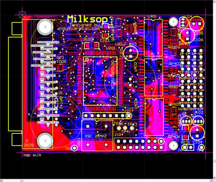
PCB
The PCB is plated through hole and measures 2.25" x 3".
- Here is a PDF showing the individual layers <-- UPDATED 2002-06-11
- Here is a ZIP of the gerber files and drill files suitable for manufacture <---- UPDATED 2002-06-11
Post Prototype 1 ECN (Engineering Change Notices)
1) Added a 820R resistor between the 3.3V rail (available on p24
of any of the 74LVXC4245s) from the regulator and the net ''p36'' (available
at the TSOP header connector). This is due to the change from databus
monitoring to determine flash busy to using the RnB pin from the flash (pin
36). This is open-drain and needs pulling up.2) The six 10R RP401 thru RP406 respacks are changed to 0R
3) Note that for the Emulation Technology TSOP header, you must fit it (via a 10 x 4 0.1" socket is recommended) to the REVERSE of the PCB. It does not connect to the same side as the Printer Port connector, just to be clear.
4) I did not fit the LEDs other than the power one in the end, so I have removed them from the parts list. Be aware these LEDs did not need a series resistor, if you plan to fit alternative LEDs you will need to fit a ~470R series resistor in one of the leads (does not matter which).
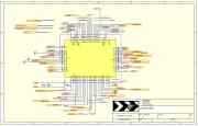
CPLD Logic
The logic to communicate with the flash using the flash protocol
is contained within the CPLD. The reasoning behind this
is that the alternative, operating the flash protocol from the PC,
would be extremely slow given the relatively slow maximum safe operating
speed of the parallel port and the relative complexity of the protocol.
With the protocol managed by the CPLD, it requires only one printer
port byte transfer to write each byte. The total chip erase/program
and readback/verify time is 45Sec for a 1Mbit chip.
Forcing/PC interface mode logic
- The state machines to manage the flash read, write and erase protocols are written in VHDL. <---- UPDATED 2002-06-16
- There is also a UCF associated with this that contains the fixed pinouts. <---- UPDATED 2002-06-16
- Here is the compiled JEDEC file ready to program into the CPLD. <---- UPDATED 2002-06-16
LPC mode logic
The CPLD Jtag connector has the following pinouts:
| 1 | +5V |
| 2 | TMS |
| 3 | TDI |
| 4 | TCK |
| 5 | (key) |
| 6 | TDO |
| 7 | Gnd |
| 8 | (no connection) |
You will need access to a Xilinx Jtag cable or other programmer capable to program the XC95108.
Programming app
A small commandline application performs the read, erase and write
actions.
Linux version
Binary RPM (installs linuxmilk
to /usr/bin) <--- UPDATED 2002-06-25
Sources <--- UPDATED 2002-06-25
If you wish to compile the sources, you will also need to download
and install the latest linux wxwindows library from http://www.wxwindows.org
Windows version
Milk.exe <--- UPDATED 2002-06-25
NTIOSUPP.DLL (needed for milk.exe)
Here is the VC++ project, note it requires
Microsoft Visual C++ 6 to compile. <--- UPDATED 2002-06-25
If you wish to compile the sources, you will also need to download
and install the latest win32 wxwindows library from http://www.wxwindows.org
Recommended build and test sequence
1) Physically connect the host chassis to Earth Ground (see the start
of the next section for more details). Skipping this step will
destroy your Milksop and maybe your PC2) fit all of the resistor packs first. Flood each side with solder, ensuring the legs are positioned over the pads. A mysterious force will tend to ensure that the pins are on the pads, it is something to do with the shape of the solder miniscus or something, anyhow, this mysterious force is on your side. Use solder braid to remove the excess solder.
3) then fit the surface mount ICs. Solder two diagonally opposite pins to hold the device in place. Again the best method is to lay a length of solder running parallel to the pins and move your soldering iron gently along flooding all the pins, then use good quality desoldering braid to remove the excess.
4) fit the rest of the components
5) confirm with a multimeter that there is a relatively high resistance between the 0V and 5V rails
6) Hook up the LPC connector to get the power, and with your multimeter monioring the 3V rail (available on pin 24 of any of the 74LVXC4245s) briefly power the host to check that you have good 3V. Note that the power LED will not light as the CPLD is unprogrammed.
7) Leave the host powered, then program the CPLD using the Xilinx tools. At the end, the power LED should light.
8) Connect up the printer port and TSOP header, run milk --readback test.bin to try to readback the contents of the TSOP. Examine test.bin to make sure it looks right.
9) Follow the instructions below to program the flash.
Sequence of operations to program in-system flash
1) Make sure the host 0V has a low impedence path to Earth Ground. If your host has a floating ground, like the X-Box, then you will destroy the milksop and/or your PC if you do not connect the host chassis to earth ground first. Your PC chassis, or the Earth pin of your power plug are good sources of true Earth ground. If you will be doing more than one host with this problem, I recommend connecting a sprung-loaded clip up to a mains plug Earth so you can easily ensure safety. If the above does not make any sense to you, stop what you are doing and find someone knowledgeable who can explain it to you. If you have access to an Oscilloscope, you can observe the problem by touching your scope probe to the ungrounded chassis of an X-Box and looking at the 50V p-p sine wave you see in front of you.
2) For the X-Box host, hold D0 of the flash databus to 0V and power
up the X-Box. It will reset twice and on the third time stay up. You
must then release D0 from ground. You can access the D0 pin from the
connector that goes out to the TSOP clip.
3) Run milk.exe, something like this: milk --program myfile.bin
This will first test that the flash can be communicated with by getting
its manufacturer ID and device type, and if successful will erase, program
and read back the contents of the device. If milk.exe cannot detect
the manufacturer ID then you have a wiring or power problem.
4) Power down the machine, remove the TSOP clip, leave the Earth
Ground connection if any for safety. Repower the host and it will be
executing the new code.
Progress 2002-06-17
|
Completed Design schematics |
||
In
Progress
|
||
|
Todo |
Credit
The amazing work of Bunnie, and folks like visor gives me encouragement with this project. Also the paid-for hackers (I believe it is Raptor and hdl) deserve a mention for their sheer hacking skills when they were the only people toiling up the mountain. Paul Bartholomew's emails have been a great help too. I salute all you people who do not give up, and make your hopes reality through sheer persistence.
¹X-Box is a registered trademark of Microsoft Corporation, nothing to do with us.