ScopeCheapmod is an SST LPC flash mounted on a standard LPC header. Every day I get a handful of emails asking me which flash chips
can be used. The answer is: SST49LF020 ONLY. Not even the -A
version of the same chip will work. Please read the CheapLPC page for
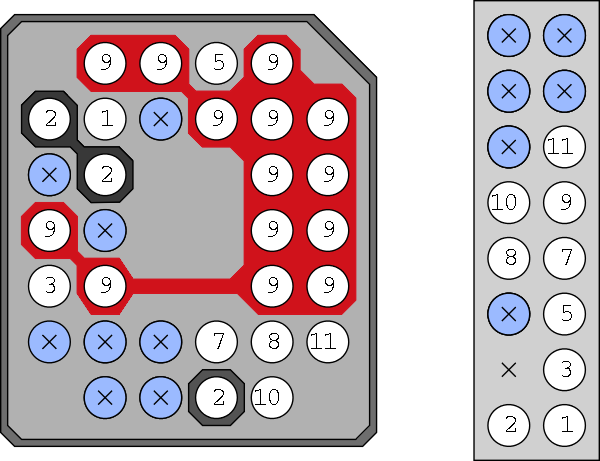
more informtion. Overview
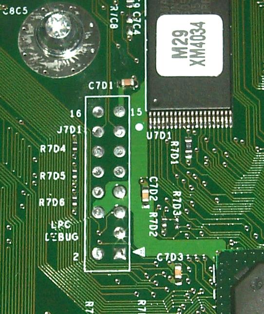
Bottom view, all of the pins are pointing up at you in this diagram Principles
Implementation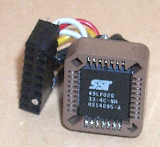
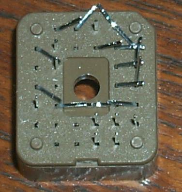
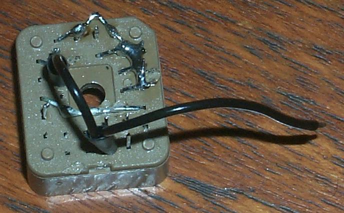
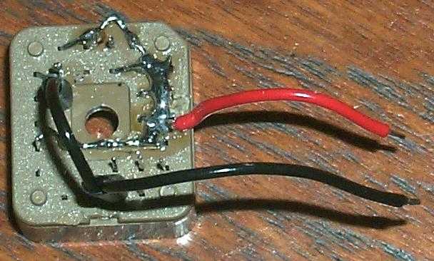
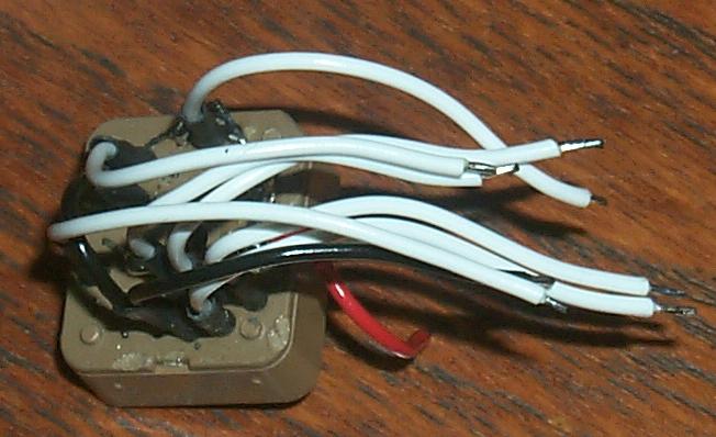
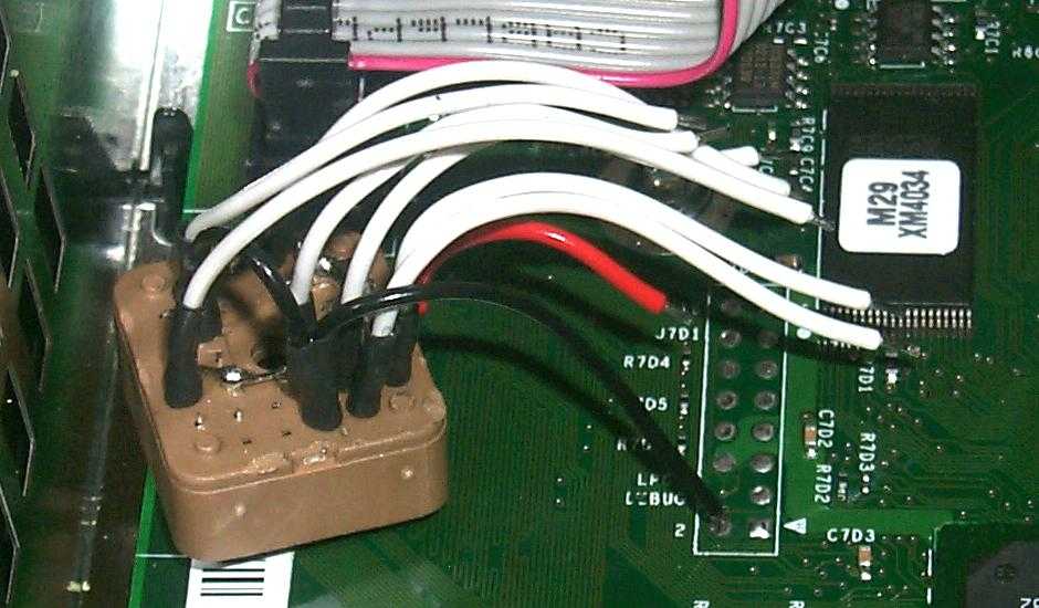
 Minimal mod with detailed fitting instructionsOn the day of the recent price reduction I went and purchased a second XBox - at GBP132 + VAT they are an amazing bargain as a generic XWindows Linux machine.I took some photos as I modded it with Cheapmod. I decided that I would be the cheapest possible kind of git this time, and so I removed the 0.1" socket, and am soldering directly to the LPC connector. Before you start, you need to have a working CheapLPC and to have programmed an SST 49LF020.
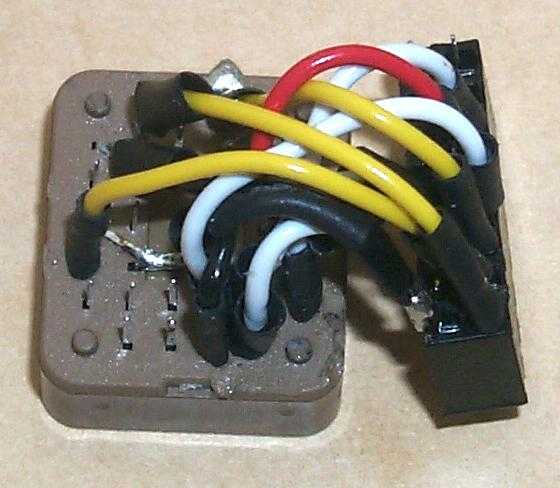
That's it, good luck! Viperman's PCBsViperman from Xboxhacker has also made some PCB images for cheapmod. I have not tested them and am merely passing them on.Viperman's Cheapmod PCB PDF Viperman's Cheapmod PCB Gerbers Max la Menace's Matrix programmer repurposingOur French friend Max la Menace was irritated by the nonstandard connector on his Matrix programmer (which is simply a CheapLPC with a battery holder). He sat down with a Multimeter and sent us the following diagram about its connector: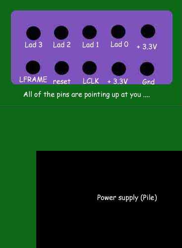
This is very clear and useful, then, it means that you can program Cheapmods using the Matrix programmer by making a small adapter. Here is the correspondence between the named pins on Max's diagram, and the numbered LPC connector pins at the top of this page
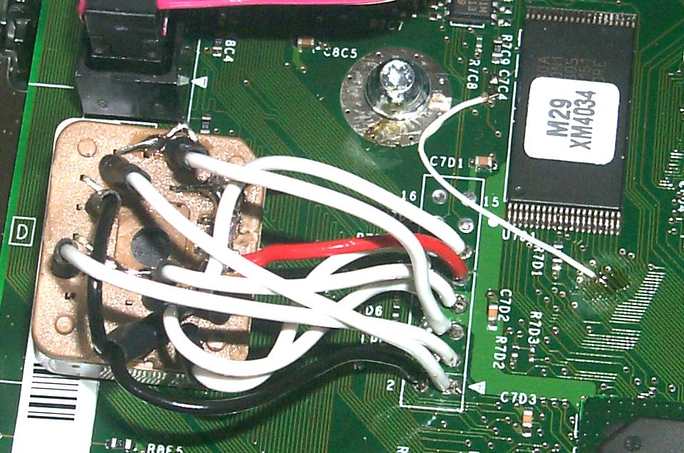
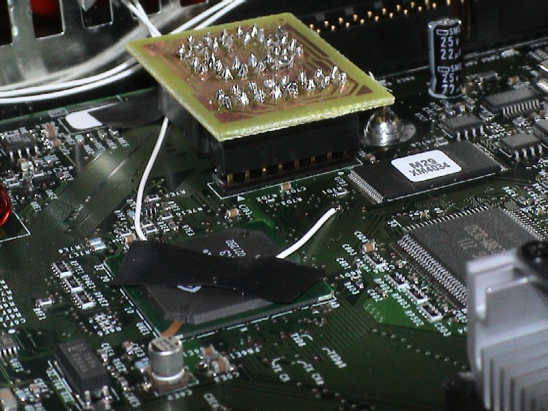
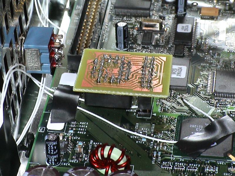
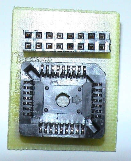
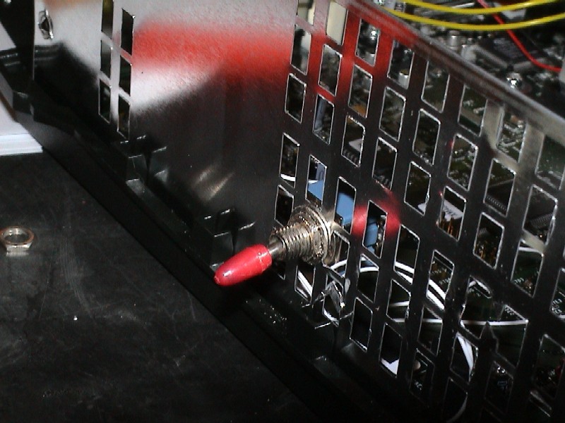
Now thanks to Max you can blow Cheapmods on your Matrix programmer. :-) Cadfael's PCB and switchCadfael (cad.fael@laposte.net) has sent the following nice pictures in from France, with a note:Andy, For the beginning I want to say that all the benefits must be sent to you for your wonderful tutorial on 'How build your homebrew LPC mod' and to Viperman from Xboxhacker for is modchip pcb. Many thanks to you. I was just concern on an easy way to plug and remove my modchip so I decided to use a pin header system to connect my modchip on the motherboard. This is just an extension to the tutorial mentioned before. It worked for me and I just want to bring my very very little stone to the scene. The only drawback is that you have to completely remove the motherboard to weld the pin header on the underside but it is a far better solution than wires (and also I think than the no solder pogo pins). It is stable, quick and easy to install, the mod can be removed with ease and replaced in seconds. No alignment, no setting up. The main benefit is that once your pin header is fitted you NEVER need to solder ANY mod into your XBOX ever again! Note also that the v1.1 consoles LPC holes are not filled in so it’s easier, just plug the header in and you're connected within minutes. For the patch wire, I chose to use the point 2 (GND) of the LPC connector cause like that I had only one 'difficult' point to weld on the motherboard instead of 2 (D0 and south side of C7C4) You can notice that I have also put a switch on the patch wire so I can easily turn on/off my modchip and boot on MS original bios or on my 'underground' one. Works fine too. I used the PCB of Viperman (works fine) with a pin header block and PLCC support for my chip. After programming my chip I only have to plug my chip on the motherboard. I sent you some photos, I suppose that it should be enough have a good idea of all the steps of my 'procedure'. Best regards from a french guy. 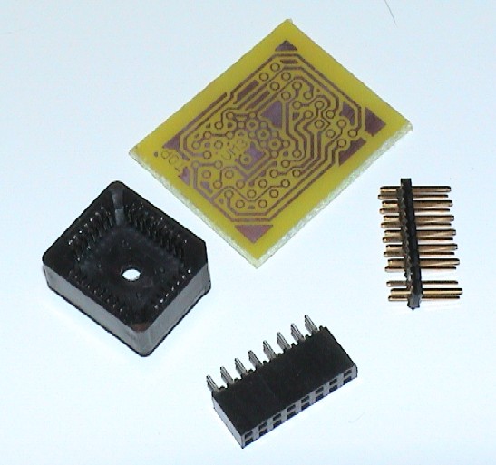
|
||||||||||||||||||||||||||||||||||||||||||||||||||||